Generation and synchronization of pulse-width modulated (PWM) waveforms for radio-frequency (RF) applications

A technology of pulse width modulation and pulse width, applied in the direction of pulse duration/width modulation, radio frequency amplifier, high frequency amplifier, etc.

Pending Publication Date: 2021-04-30
MASSACHUSETTS INST OF TECH
View PDF5 Cites 0 Cited by
  • Summary
  • Abstract
  • Description
  • Claims
  • Application Information

AI Technical Summary

Problems solved by technology

However, digital TMNs exhibit limited tuning resolution and thus limited accuracy with which impedance matching can be achieved

Method used


Image

  • Generation and synchronization of pulse-width modulated (PWM) waveforms for radio-frequency (RF) applications
  • Generation and synchronization of pulse-width modulated (PWM) waveforms for radio-frequency (RF) applications
  • Generation and synchronization of pulse-width modulated (PWM) waveforms for radio-frequency (RF) applications

Examples


Embodiment Construction

[0086] Table 1 summarizes a list of acronyms employed throughout this specification to aid in understanding the described embodiments:

[0087]

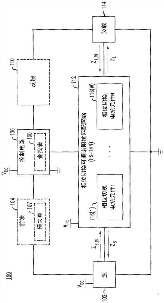
[0088] The described embodiments are directed to a phase switched tunable matching network (PS-TMN) and a phase switched impedance modulated amplifier (PSIM). Both the phase-switched tunable matching network and the phase-switched impedance modulated amplifier include phase-switched variable network reactive elements. When configured in the context of PS-TMN and phase-switched impedance-modulated amplifiers, such phase-switched variable network reactive elements provide fast, high-bandwidth, continuous impedance matching over a wide impedance range while not requiring high bias It operates efficiently at high power levels with no set voltage or current. PS-TMN can be used alone or in combination with other matching techniques such as discrete switched reactance banks.

[0089] PS-TMN can be used in a variety of reconfigurable an...


PUM


Abstract

Described are concepts, systems, circuits and techniques directed toward methods and apparatus for generating one or more pulse width modulated (PWM) waveforms with the ability to dynamically control pulse width and phase with respect to a reference signal.

Description

Background technique [0001] As known in the art, impedance matching networks are commonly used to maximize power transfer within many radio frequency (RF) and microwave systems. For example, in an RF transmitter, an impedance matching network may be used to provide impedance matching from the output impedance of an RF power amplifier (PA) to the impedance of an RF load (eg, an antenna). This impedance matching increases the power transferred, reduces power loss, and reduces or eliminates the need for additional circuit components (eg, isolators, etc.). [0002] One type of impedance matching network is called a tunable impedance matching network (TMN), sometimes called an automatic antenna tuning element. A conventional TMN can be implemented as a single-element or lumped-element reactive network, where at least one of the reactive elements is a variable (e.g., tunable) element such that at a specific frequency Or the impedance can be modified over a frequency range. The re...

Claims


Application Information

Patent Timeline
IPC IPC(8): H03F1/02H03F1/56H03F3/19H03F3/193H03F3/21H03F3/217H03F3/24H03H7/38
CPCH03F3/193H03F3/217H03H7/38H03H19/004H03K7/08H03F3/2176H03F1/565H03F1/0205H03F3/245H03F2200/451H03F2200/351H03L7/0814
Inventor A·S·朱尔科夫D·J·佩罗
Owner MASSACHUSETTS INST OF TECH
Why Eureka
Try Eureka