Kitchen garbage solid-liquid separation device based on rotary extrusion

A technology for solid-liquid separation and kitchen waste, which is applied in the direction of garbage drying, presses, drying gas arrangement, etc., can solve the problems of perishability, food waste is perishable, mixed solid and liquid, complex sewage treatment, etc.

Active Publication Date: 2021-05-04
安必思环保科技(淄博)有限公司
View PDF9 Cites 2 Cited by
  • Summary
  • Abstract
  • Description
  • Claims
  • Application Information

AI Technical Summary

Problems solved by technology

Kitchen waste contains extremely high moisture and organic matter, which is easy to rot and produce bad smell
[0003] At present, some places adopt the waste sorting method that residents classify and then sort and put away. The characteristics of food waste, which is perishable and mixed with solid and liquid, are not considered. There i

Method used


Image

  • Kitchen garbage solid-liquid separation device based on rotary extrusion
  • Kitchen garbage solid-liquid separation device based on rotary extrusion
  • Kitchen garbage solid-liquid separation device based on rotary extrusion

Examples


Embodiment 1

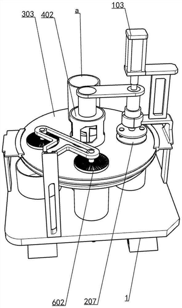
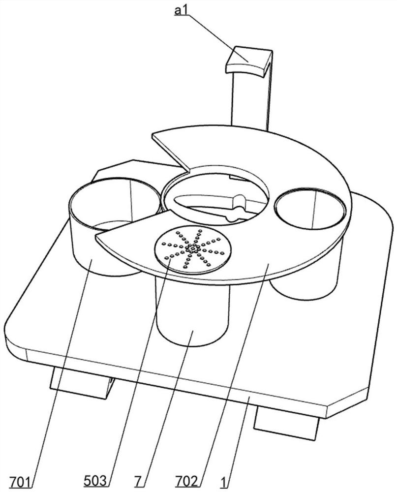
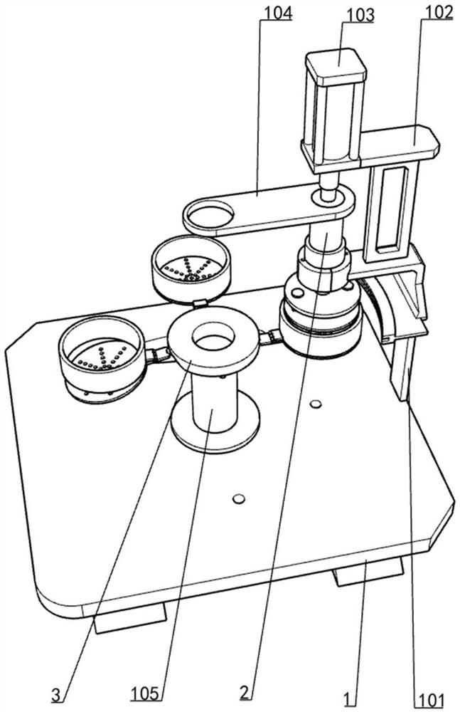
[0034] Such as figure 1 and figure 2As shown, a solid-liquid separation device for kitchen waste based on rotary extrusion includes a base 1, a support plate 101, a bracket 102, a cylinder 103, a horizontal plate 104, a support pipe 105, a waste water bucket 7, a solid material collection bucket 701, Arc-shaped plate 702, L curved rod a1, barrel a, extrusion assembly, station plate assembly, rotation guide assembly and filter assembly, support plate 101 and support pipe 105 are installed on the upper side of base 1, and support plate 101 is along the base 1 There are two left and right symmetrically arranged, the lower end of the support pipe 105 is fixedly connected to the center of the base 1, the lower side of the support 102 is fixedly connected to the upper side of the support plate 101, the cylinder 103 is installed on the left upper side of the support 102, and the horizontal plate 104 The upper right side is fixedly connected to the lower end of the push rod of the c...

Embodiment 2

[0037] Specific reference image 3 Figure 4 and Figure 5 , on the basis of Embodiment 1, the extrusion assembly includes a lower pressure column 2, a rotating ring 2011, a guide pin 201, an upper pressure plate 202, a fixed track sleeve 203 and a sliding plate assembly, and the upper end of the lower pressure column 2 Fixedly connected to the right end of the horizontal plate 104, the lower end of the lower pressure column 2 is rotatably connected to the rotating ring 2011, the guide sliding pin 1 201 traverses the middle of the rotating ring 2011 and extends to both ends, and the outer wall of the fixed track sleeve 203 is fixedly connected to the bracket 102 The lower end of the rotating ring 2011 passes through the fixed track cover 203, the guide pin 1 201 slides along the groove track in the fixed track cover 203, the upper platen 202 is fixedly connected to the lower end of the rotating ring 2011, and the center of the upper platen 202 A spline groove is formed, and ...

Embodiment 3

[0050] Specific reference Figure 12 On the basis of Embodiment 2, it also includes a slide bar 6, a curved bar 601, a fan one 602 and a fan two 603, the lower end of the slide bar 6 is fixedly connected to the left front side of the base 1, and the curved bar 601 is T-shaped , the left front end of the curved bar 601 slides in the chute on the slide bar 6, the right front end of the curved bar 601 is fixedly connected with a fan one 602, the left rear end of the curved bar 601 is fixedly connected with a fan two 603, and the fan two 603 is fixedly connected A solid material collection bucket 701 is placed below, and a waste water bucket 7 is placed directly below the fan one 602 .

[0051] When the extruded rubbish is brought to the fan one 602 by the ring bucket 302, the fan one 602 will blow the sewage in the garbage in the ring bucket 302 into the bucket by blowing air, and then realize the further separation of the moisture, and when the garbage When the ring bucket 302 ...


PUM


Abstract

The invention relates to a garbage treatment device, in particular to a kitchen garbage solid-liquid separation device based on rotary extrusion. The technical purpose of the invention is to provide the kitchen garbage solid-liquid separation device based on rotary extrusion, which can realize quantitative feeding and reciprocating rotation in an extrusion process. According to the technical implementation scheme of the invention, the kitchen garbage solid-liquid separation device based on rotary extrusion comprises a base, two support plates, a support pipe and the like; the support plates and the support pipe are arrange on the base, the two support plates are symmetrically arranged along the periphery of the base, and one end of the support pipe is fixedly connected with the center position of the base. The solid-liquid kitchen garbage can rotate and extrude garbage simultaneously during separation of solid-liquid kitchen garbage through cooperation of an extrusion assembly and a cylinder, so that filter holes are not easy to be blocked in the separation process, and extrusion of the kitchen garbage can be more thorough.

Description

technical field [0001] The invention relates to a garbage treatment device, in particular to a solid-liquid separation device for kitchen waste based on rotary extrusion. Background technique [0002] Kitchen waste refers to the waste generated in the daily life of residents and activities such as food processing, catering services, and unit meals, including discarded vegetable leaves, leftovers, leftovers, fruit peels, eggshells, tea dregs, bones, etc. The main sources are home kitchens, restaurants, restaurants, canteens, markets and other industries related to food processing. Kitchen waste contains extremely high moisture and organic matter, which is easy to rot and produce bad smell. [0003] At present, some places adopt the waste sorting method that residents classify and then sort and put away. The characteristics of food waste, which is perishable and mixed with solid and liquid, are not considered. There is no special container for storage during the sorting proce...

Claims


Application Information

Patent Timeline
IPC IPC(8): B30B9/04B30B9/06B30B15/00B30B9/26F26B21/00
CPCB30B9/042B30B9/06B30B15/00B30B9/26F26B21/004F26B2200/04Y02W30/10
Inventor 王东
Owner 安必思环保科技(淄博)有限公司
Why Eureka
Try Eureka