
Stepless locking device for gate

A locking device and gate technology, applied in water conservancy projects, marine engineering, coastline protection, etc., can solve the problems of free fall of the gate, no resonance of the gate, safety accidents, etc.

Pending Publication Date: 2021-05-04
CHANGJIANG SURVEY PLANNING DESIGN & RES
View PDF0 Cites 0 Cited by
  • Summary
  • Abstract
  • Description
  • Claims
  • Application Information

AI Technical Summary

Problems solved by technology

[0002] During the lifting process of the gate of water conservancy projects, the gate falls freely due to the failure of the lifting equipment; or when the gate stops at a certain opening, the water flow and the gate excite resonance due to the gate passing through the water, resulting in the resonance damage of the gate and its lifting equipment, resulting in safety ACCIDENT
[0003] At present, large-scale gate lifting equipment is usually operated by a hydraulic hoist. After the operation is completed, the gate will slide due to internal leakage of the oil cylinder. When the gate falls to a certain distance, the hydraulic hoist will be started again to lift the gate. Currently, there is no other The method can keep the gate stable at a certain position for a long time without sliding down; if the hoisting equipment of the large gate is operated by a wire rope winch hoist, after the operation is completed, the orifice passes through the water, the water flow hits the gate, and the water flow and the gate resonate. Passively choose the opening to avoid the resonance area, and there is no other way to make the gate not resonate at any opening

Method used


Image

  • Stepless locking device for gate
  • Stepless locking device for gate
  • Stepless locking device for gate

Examples


Embodiment Construction

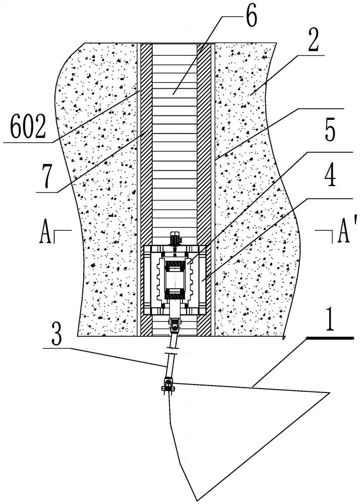
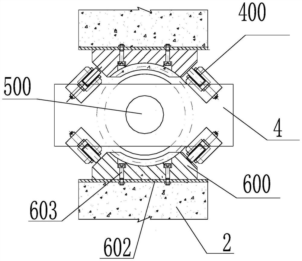
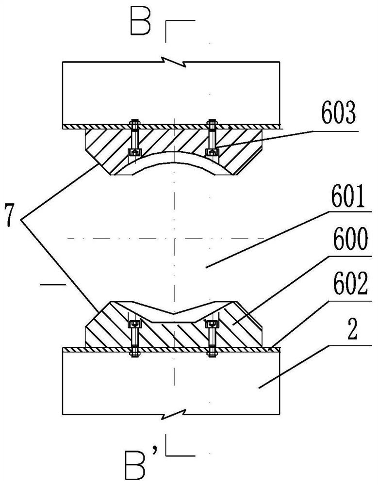
[0031] The present invention will be further described below in conjunction with the accompanying drawings. attached Figure 1 to Figure 13 All are drawings of embodiments, drawn in a simplified manner, and are only used for the purpose of clearly and concisely illustrating the embodiments of the present invention. The following technical solutions shown in the drawings are specific solutions of the embodiments of the present invention, and are not intended to limit the scope of the claimed invention. Based on the embodiments of the present invention, all other embodiments obtained by persons of ordinary skill in the art without creative efforts fall within the protection scope of the present invention.

[0032] In the description of the present invention, it should be understood that the orientations or positional relationships indicated by the terms "upper", "lower", "inner", "outer", "left", "right" etc. are based on those shown in the accompanying drawings. Orientation o...


PUM


Abstract

The invention provides a stepless locking device for a gate. The stepless locking device comprises a stress connecting rod, a retainer, a power stud and a bearing nut, wherein a stud body of the power stud is arranged in the retainer, the upper end and the lower end of the stud body are connected with the retainer through rack bearings, and a power device of the power stud controls the stud body to rotate in the retainer; the bearing nut is vertically fixed to a hydraulic structure, a limiting sliding way is vertically formed in the inner wall of the bearing nut, the stud body and the retainer are both arranged in a threaded inner cavity of the bearing nut, an outer thread of the stud body is in close fit with an inner thread of the bearing nut, and the retainer is in sliding connection with the limiting sliding way in the inner wall of the bearing nut through an adjusting wheel; and one end of the stress connecting rod is rotationally connected with the stud body, and the other end of the stress connecting rod is connected with the gate through a hinge. The stepless locking problem of the gate at any position is solved, the accident of free falling of the gate due to the main lifting fault of the gate is prevented, and resonance of the gate during water passing at a certain opening degree is also avoided.

Description

technical field [0001] The invention relates to a safety locking device for a gate in a water conservancy project, in particular to a stepless locking device for a gate that can safely lock a gate at any position within the range of the gate's opening stroke. Background technique [0002] During the lifting process of the gate of water conservancy projects, the gate falls freely due to the failure of the lifting equipment; or when the gate stops at a certain opening, the water flow and the gate excite resonance due to the gate passing through the water, resulting in the resonance damage of the gate and its lifting equipment, resulting in safety ACCIDENT. [0003] At present, large-scale gate lifting equipment is usually operated by a hydraulic hoist. After the operation is completed, the gate will slide due to internal leakage of the oil cylinder. When the gate falls to a certain distance, the hydraulic hoist will be started again to lift the gate. Currently, there is no oth...

Claims


Application Information

Patent Timeline
IPC IPC(8): E02B7/36E02B7/52
CPCE02B7/36E02B7/52
Inventor 李克华宋志忠钱军祥胡剑杰韩争光
Owner CHANGJIANG SURVEY PLANNING DESIGN & RES
Learn More