Finned evaporator and production process thereof

A technology of finned evaporator and production process, applied in the direction of evaporator/condenser, tubular element, damage protection, etc., can solve the problems of fin deformation, low heat absorption efficiency, damage, etc., to achieve convenient installation, flexible equipment and practical effect

Active Publication Date: 2021-05-04
镇江市威胜电气有限公司
View PDF5 Cites 0 Cited by
  • Summary
  • Abstract
  • Description
  • Claims
  • Application Information

AI Technical Summary

Problems solved by technology

When the existing evaporator is placed outdoors, it often has the problem of difficulty in defrosting when it encounters a frosty outdoor environment. According to the Chinese patent literature, the announcement number is CN111595070A. A finned evaporator is provided to improve the heat absorption of the refrigerant tube Effect, high heat absorption efficiency, good air flow performance, large contact area, can better adapt to environmental changes, high defrosting efficiency, and is not easy to attach garbage, but under long-term low-temperature use, the moisture on the surface will be in the external environment or excessive heat exchange Frost will also occur under certain circumstances. After the frost occurs, if it is not cleaned in time, the heat absorption efficiency will be low. Because the fin structure of the conventional evaporator is also very fixed, it is difficult to make more adjustments. During installation and frost treatment It is also easy to cause deformation or damage to the fins, and only artificial thawing will also be time-consuming, labor-intensive and unclean.

Method used


Image

  • Finned evaporator and production process thereof
  • Finned evaporator and production process thereof
  • Finned evaporator and production process thereof

Examples


Embodiment Construction

[0035] In order to further illustrate the various embodiments, the present invention provides accompanying drawings, which are part of the disclosure of the present invention, and are mainly used to illustrate the embodiments, and can be used in conjunction with the relevant descriptions in the specification to explain the operating principles of the embodiments, for reference Those of ordinary skill in the art should be able to understand other possible implementations and advantages of the present invention. The components in the figures are not drawn to scale, and similar component symbols are generally used to represent similar components.

[0036] According to an embodiment of the present invention, a finned evaporator and a production process thereof are provided.

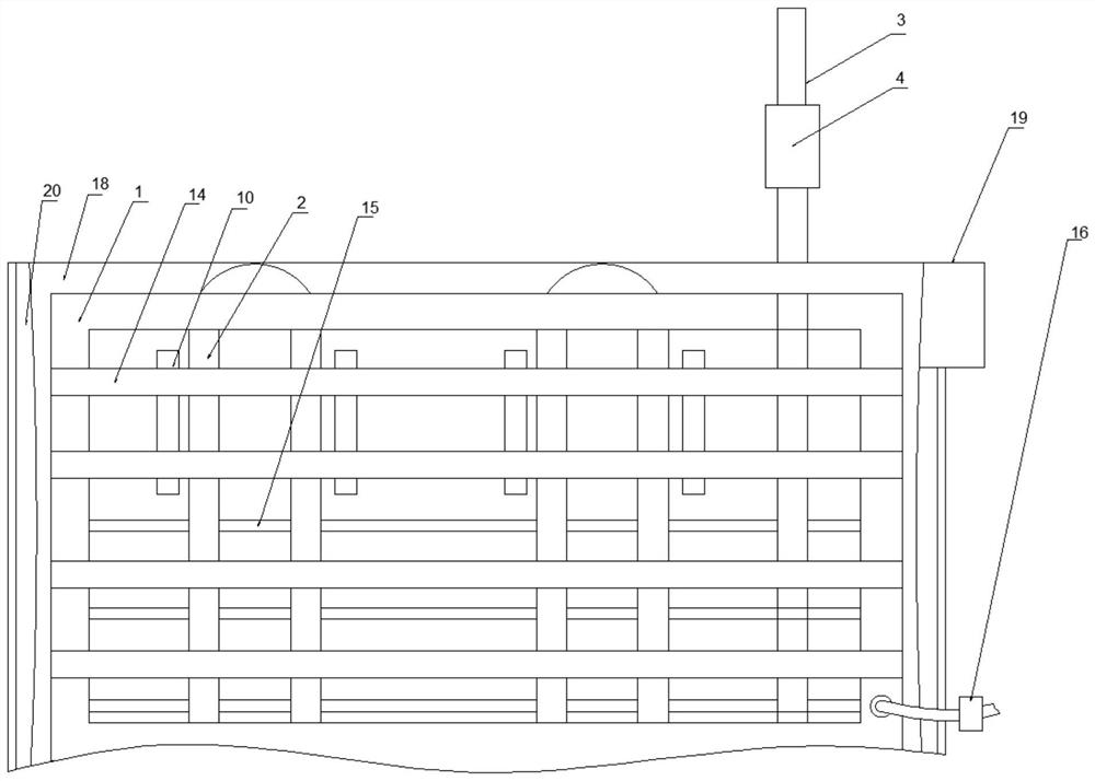
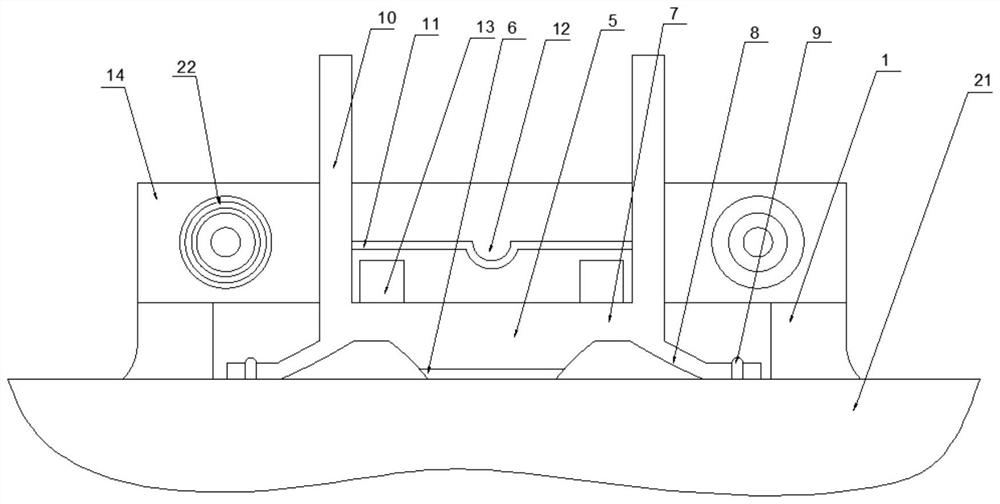
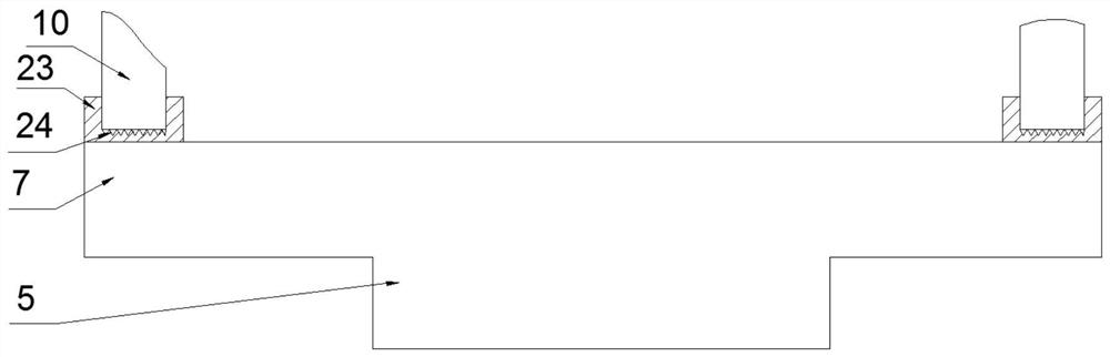
[0037] Such as Figure 1-5 As shown, the finned evaporator according to the embodiment of the present invention includes a frame 1, a coil 2 matched with it is provided inside the frame 1, and a heat shrinkab...


PUM


Abstract

The invention discloses a finned evaporator and production process thereof. The finned evaporator comprises a frame, wherein coil pipes matched with the frame are arranged in the frame, a heat shrink tube matched with the coil pipe is arranged at one end of the coil pipe, a flaring connecting pipe is arranged between the heat shrink tube and the coil pipe, the outer wall of the coil pipe is sleeved with a plurality of heat dissipation sleeves matched with the coil pipe, a heat conduction connecting sleeve is arranged between the heat dissipation sleeves and the coil pipes, extension sleeves matched with the heat dissipation sleeves are fixedly connected to the two sides of the heat dissipation sleeves, a plurality of heat dissipation extension pieces matched with the extension sleeves are arranged on the sides, away from the heat dissipation sleeves, of the extension sleeves, a plurality of evenly-distributed fixed-section fixing pins are arranged in the heat dissipation extension pieces in a penetrating mode, fins matched with the extension sleeves are arranged outside the extension sleeves in a sleeving mode, and vibration frame pieces matched with the heat dissipation sleeves are symmetrically arranged between every two fins. The finned evaporator has the beneficial effects that the fins can be well adjusted during the whole use period of the finned evaporator, so that the finned evaporator is more flexible and practical.

Description

technical field [0001] The invention relates to the field of evaporators, in particular to a finned evaporator and a production process thereof. Background technique [0002] Evaporation is the physical process of converting a liquid to a gaseous state. Generally speaking, an evaporator is an object that converts a liquid substance into a gaseous state. There are a large number of evaporators in the industry, and the evaporator used in the refrigeration system is one of them. The evaporator is a very important part of the four major components of refrigeration. The low-temperature condensed liquid passes through the evaporator, exchanges heat with the outside air, vaporizes and absorbs heat, and achieves the effect of refrigeration. The evaporator is mainly composed of two parts: a heating chamber and an evaporation chamber. The heating chamber provides the heat needed for evaporation to the liquid, which promotes the boiling and vaporization of the liquid; the evaporatio...

Claims


Application Information

Patent Timeline
Patent Type & Authority Applications(China)
IPC IPC(8): F25B39/02F25B47/00F28F1/32F28F19/00B23P15/26
CPCF25B39/02F25B47/006F28F1/32F28F19/00B23P15/26F25B2339/02
Inventor 唐勇
Owner 镇江市威胜电气有限公司
Why Eureka
Try Eureka