
Cylinder cover oil sprayer hole ring groove coaxiality detection device

A technology of injector hole and detection device, which is applied to measurement devices, instruments, etc., achieves the effects of high compatibility, avoidance of scratches, and easy disassembly and replacement.

Pending Publication Date: 2021-05-04
GUANGXI YUCHAI MASCH CO LTD
View PDF1 Cites 0 Cited by
  • Summary
  • Abstract
  • Description
  • Claims
  • Application Information

AI Technical Summary

Problems solved by technology

[0005] Aiming at the problems existing in the prior art, the present invention provides a detection device for the coaxiality of the annular groove of the cylinder head fuel injector, which has the function of expanding the core. The matching gap between the tool and the workpiece is zero, the positioning is more accurate and reliable, and it is not easy to wear, which well avoids the shortcomings of the existing inspection tool structure

Method used


Image

  • Cylinder cover oil sprayer hole ring groove coaxiality detection device
  • Cylinder cover oil sprayer hole ring groove coaxiality detection device
  • Cylinder cover oil sprayer hole ring groove coaxiality detection device

Examples


Embodiment 1

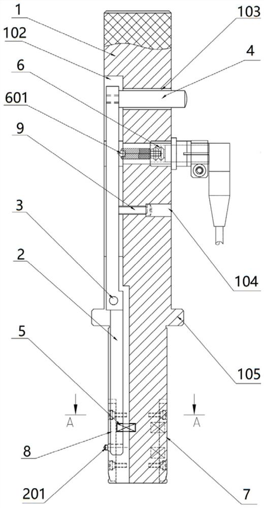
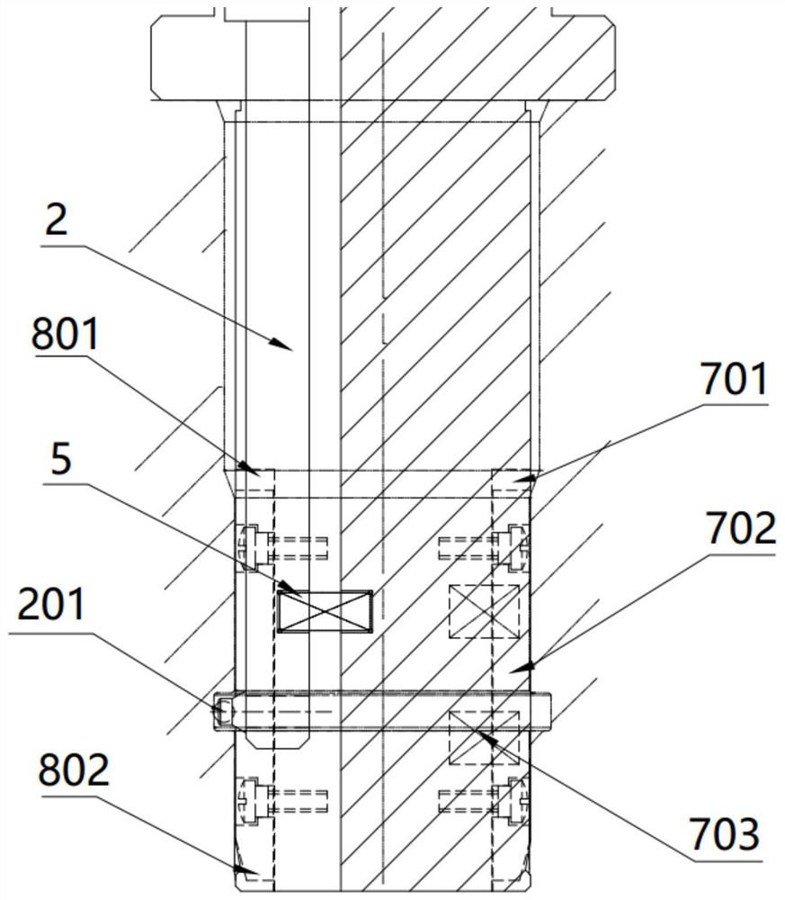
[0028] According to a specific embodiment of the program, a cylinder head fuel injector annular groove coaxiality detection device, such as Figure 1-4 As shown, it includes a mandrel 1 and a measuring head 201 arranged at the lower part of the mandrel 1 for measuring the injector annular groove 11. The main point is that a core expansion mechanism 7 is provided on the outer surface of the lower part of the mandrel 1 , the core expansion mechanism 7 is a movable mechanism that can be tightened and condensed by an external force, so that the core expansion mechanism 7 can match the inner diameter of the injector hole 10 . The positioning part of the detection device is equipped with a mechanism with the function of expanding the core, and the circular arc and the inner diameter of the injector hole 10 are used for expansion and positioning. It is not necessary to replace the positioning mandrel or positioning sleeve during use, and the inspection tool and the workpiece can also ...

Embodiment 2

[0034] On the basis of Embodiment 1, this embodiment further optimizes the operation mode of the device, the specific differences are: as figure 1As shown, a third vertical groove 102 is vertically opened on one side of the mandrel 1, and a swing rod 2 is arranged in the third vertical groove 102, and the middle part of the swing rod 2 is connected with the first fastening pin 3 The sidewalls of the three vertical grooves 102 are hinged, and a gap for making way for the swing rod 2 to rotate is provided between the fork 2 and the third vertical groove 102; The top of 1 is provided with a transverse groove 103, and an extruding rod 4 is arranged in the transverse groove 103. One end of the extruding rod 4 is connected to the upper part of the swing rod 2, and the other end extends out of the mandrel 1; The second compression spring 5 is arranged in the gap between the lower part of the swing rod 2 and the third vertical groove 102; The outer lateral extension, by pressing or l...


PUM


Abstract

The invention discloses a cylinder cover oil sprayer hole ring groove coaxiality detection device which comprises a core rod and a measuring head arranged on the lower portion of the core rod and used for measuring an oil sprayer ring groove. A core expansion mechanism is arranged on the outer side face of the lower portion of the core rod, and the core expansion mechanism is a movable mechanism which expands and can be condensed through external force. And the core expansion mechanism can be matched with the inner diameter of the oil sprayer hole. The device has a core expansion function, the fit clearance between the detection tool and a workpiece can be zero without replacing the device with a positioning core rod or a positioning sleeve when the device is used, the positioning is more accurate and reliable, the detection tool is not easy to wear, and the defects of the existing detection tool structure are well avoided.

Description

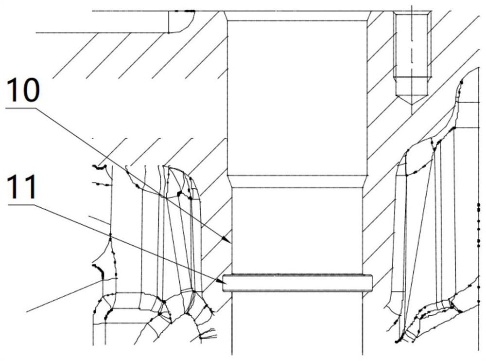
technical field [0001] The invention relates to the technical field of engine detection, in particular to a detection device for the coaxiality of an annular groove of an injector of a cylinder head. Background technique [0002] The O-shaped groove in the injector hole of the cylinder head is used for installing the sealing ring. Unqualified, it is easy to cause uneven compression of the sealing ring after assembly, and it is easy to cause poor sealing and water leakage. Therefore, whether the coaxiality of the ring groove meets the process requirements will directly affect the sealing effect and have a significant impact on the performance of the engine. like figure 1 As shown, the diameter of the injector hole 10 in the cylinder head is generally between 20 and 30mm, and the diameter is not large, while the sealing O-ring groove 11 is generally in the middle and lower part of the injector hole, and there is a certain distance from the top and bottom of the cylinder head...

Claims


Application Information

Patent Timeline
Patent Type & Authority Applications(China)
IPC IPC(8): G01B21/24
CPCG01B21/24
Inventor 谢卫军蒋金文
Owner GUANGXI YUCHAI MASCH CO LTD
Learn More