
Detection system and detection method of display panel

A technology for display panels and inspection systems, applied in static indicators, testing optical performance, optical testing flaws/defects, etc. Low brightness and other problems, to avoid the inability to accurately judge the location of dead pixels and improve the accuracy

Pending Publication Date: 2021-05-04
乐金显示光电科技(中国)有限公司
View PDF9 Cites 1 Cited by
  • Summary
  • Abstract
  • Description
  • Claims
  • Application Information

AI Technical Summary

Problems solved by technology

[0004] However, if the brightness uniformity of the display panel is poor due to its own defects (that is, there are obvious differences in the brightness in the display area, the local brightness is high, and the local brightness is low), then it will not be possible to accurately determine whether there is an over-bright or over-dark area. Dead pixels, resulting in reduced accuracy of detection results

Method used


Image

  • Detection system and detection method of display panel
  • Detection system and detection method of display panel
  • Detection system and detection method of display panel

Examples


Embodiment Construction

[0060] The present invention will be further described in detail below in conjunction with the accompanying drawings and embodiments. It should be understood that the specific embodiments described here are only used to explain the present invention, but not to limit the present invention. In addition, it should be noted that, for the convenience of description, only some structures related to the present invention are shown in the drawings but not all structures.

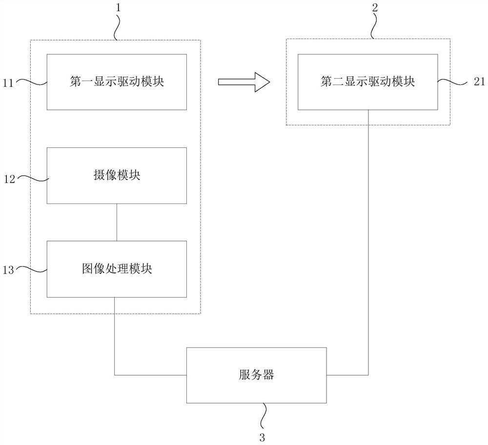
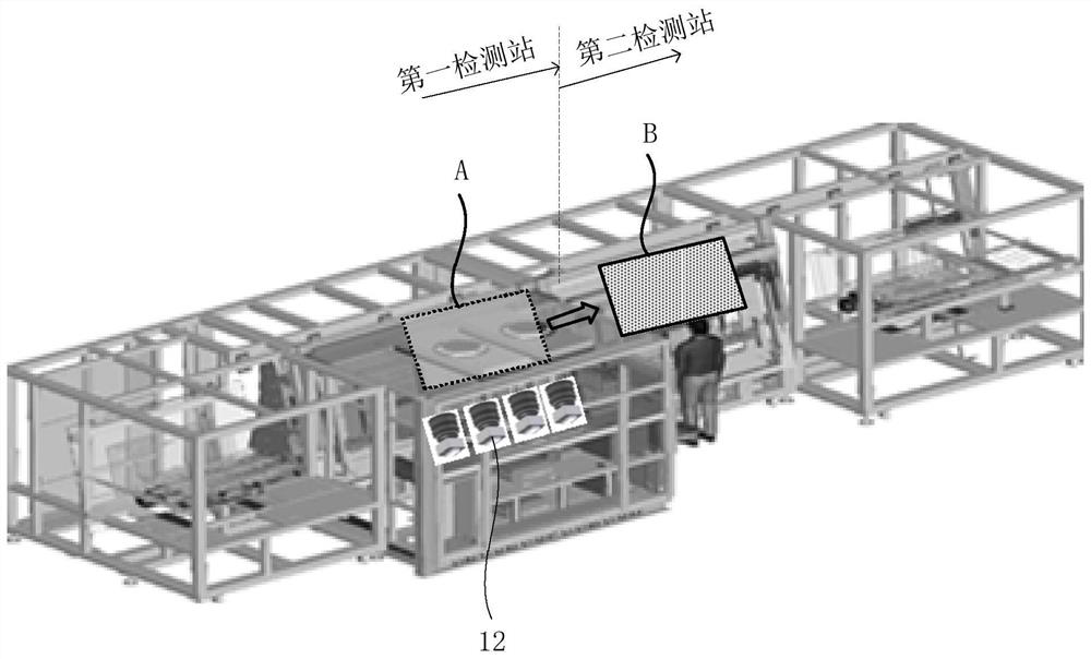
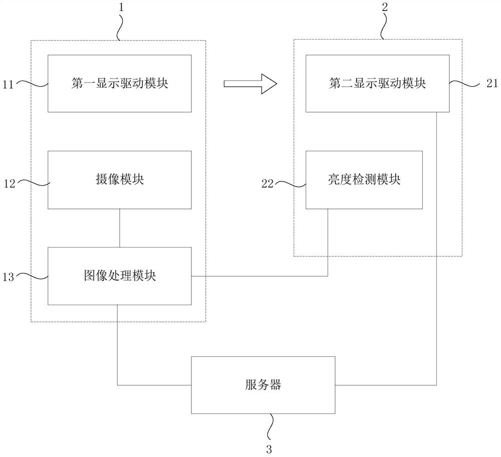
[0061] figure 1 It is a schematic structural diagram of a detection system for a display panel provided by an embodiment of the present invention, see figure 1 , the detection system of the display panel provided by the embodiment of the present invention includes a first detection station 1, a second detection station 2 and a server 3; the display panel performs display detection at the first detection station 1 and the second detection station 2 in sequence; the first detection Station 1 includes a first displa...


PUM


Abstract

The embodiment of the invention discloses a detection system and a detection method of a display panel. The detection system comprises a first detection station, a second detection station and a server, in the detection stage of the display panel, a first display driving module is used for driving the display panel to display a first picture; a camera module is used for shooting the first picture to generate image information; an image processing module used for generating identification information according to the image information and sending the identification information to the server; the identification information comprises a bad name used for identifying the brightness information of the display panel; the server is used for receiving the identification information and sending the identification information to the second display driving module; a second display driving module is used for driving the display panel to display a second picture according to the identification information so as to perform display detection on the display panel according to the second picture; and the brightness uniformity of the second picture is greater than that of the first picture. The detection system can improve the accuracy of a detection result.

Description

technical field [0001] Embodiments of the present invention relate to a display panel detection technology, and in particular, to a display panel detection system and detection method. Background technique [0002] Display panels (such as organic light-emitting diode display panels) generally need to undergo quality inspection after the production is completed, so as to ensure that the manufactured products are high-quality products. [0003] When the display panel is performing display detection, the driver chip is usually not bound. Therefore, the detection line of the existing display panel first lights up the display panel through the display driver (module), and then judges whether the display panel is There are dead pixels (defective sub-pixels). If the luminance of each sub-pixel is within the standard luminance range (that is, the luminance of the entire display panel is relatively uniform), the position of the dead pixel can be determined more accurately. [0004]...

Claims


Application Information

Patent Timeline
Patent Type & Authority Applications(China)
IPC IPC(8): G01N21/88G01M11/02G09G3/3208
CPCG01N21/88G01M11/02G09G3/3208
Inventor 宋元根吴少辉
Owner 乐金显示光电科技(中国)有限公司
Learn More