
A sheath trimmer

A technology for trimmers and sheaths, applied in metal processing, etc., can solve problems such as low work efficiency, low production efficiency, and impact on production efficiency, and achieve the effects of improving production efficiency, increasing torsional force, and improving use stability

Active Publication Date: 2022-07-05
浙江中田电子护套有限公司
View PDF0 Cites 0 Cited by
  • Summary
  • Abstract
  • Description
  • Claims
  • Application Information

AI Technical Summary

Problems solved by technology

However, the way of manual cutting, the work efficiency is relatively low, thus affecting the production efficiency
[0004] For the related technologies mentioned above, the inventor believes that there is a defect of low production efficiency

Method used


Image

  • A sheath trimmer
  • A sheath trimmer
  • A sheath trimmer

Examples


Embodiment Construction

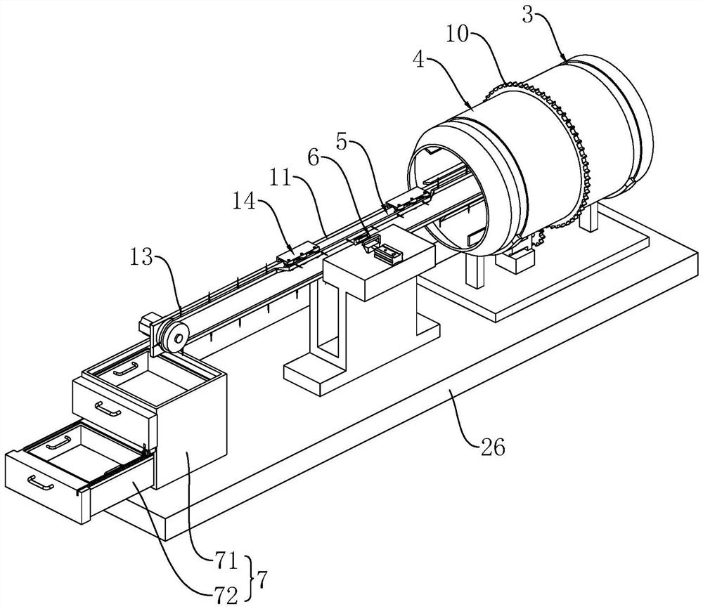
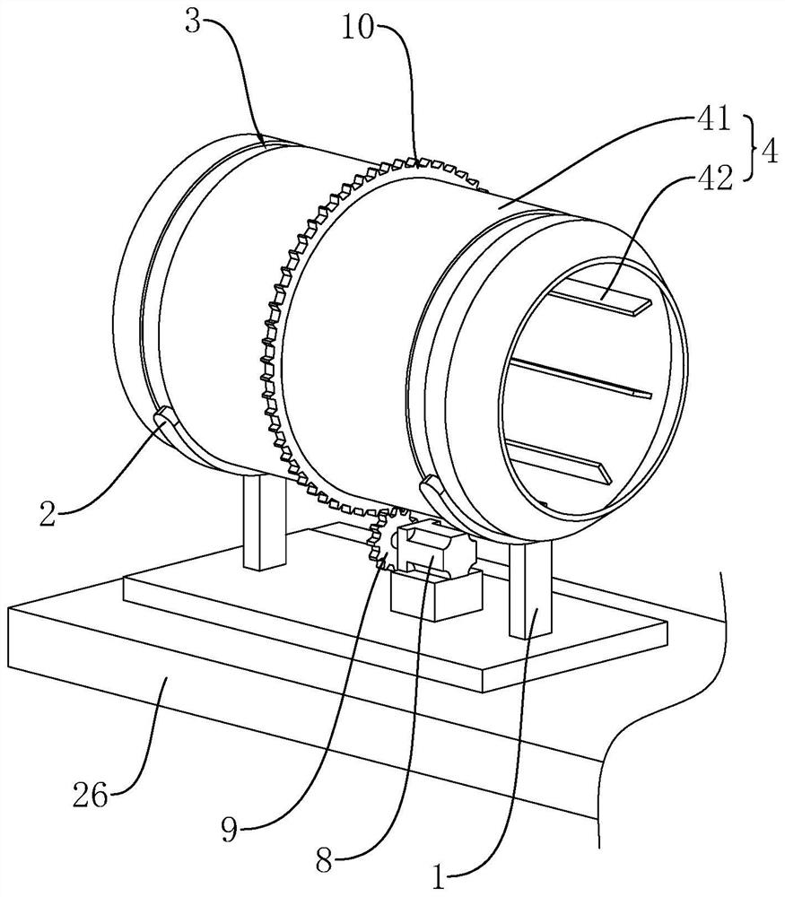
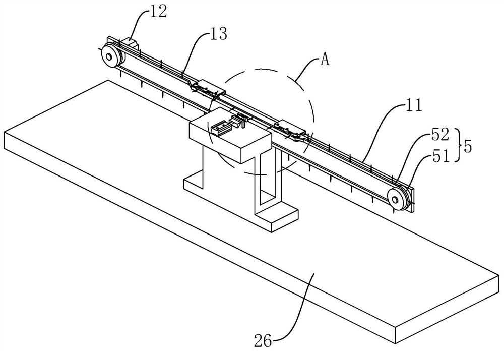
[0037] Attached to the following Figure 1-5 This application will be described in further detail.

[0038] The embodiment of the present application discloses a sheath trimmer. refer to figure 1 , the sheath trimmer includes a workbench 26, and the upper end surface of the workbench 26 is provided with a feeding mechanism 4, a conveying mechanism 5, a cutting mechanism 6 and a material receiving mechanism 7 in sequence. The feeding mechanism 4 is used for feeding the sheath and transporting the sheath to the conveying mechanism 5, which is used for transporting the sheath. The cutting mechanism 6 is used for cutting off the closed end of the sheath on the conveying mechanism 5, and the receiving mechanism 7 is used for collecting the finished sheath.

[0039] refer to figure 1 and figure 2 The upper end surface of the workbench 26 is vertically fixedly connected with two support rods 1, and the upper end of each support rod 1 is fixedly connected with a guide rod 2, the g...


PUM


Abstract

The present application relates to a sheath trimmer, which relates to the technical field of sheath production and processing equipment, comprising a workbench, on which a feeding mechanism, a conveying mechanism, a cutting mechanism and a receiving mechanism are arranged in sequence. The cutting mechanism includes a fixed knife and a moving knife. The moving knife is horizontally slidably arranged on the worktable and is used to move toward the fixed knife. A cylinder is provided on the worktable, and the piston end of the cylinder is connected to the fixed knife. The moving knife is connected. By using the feeding mechanism to send the sheath to the conveying mechanism, and then transporting the sheath through the conveying mechanism, and then driving the moving knife to move toward the fixed knife through the air cylinder, and then realizing the closed end of the sheath through the mutual cooperation of the fixed knife and the moving knife. After cutting, the finished sheath can be collected by the receiving mechanism, so as to realize the automatic cutting and collection of the sheath, thereby effectively improving the production efficiency.

Description

technical field [0001] The present application relates to the field of sheath production and processing equipment, in particular to a sheath trimmer. Background technique [0002] The sheath is mainly used for the outer insulation protection of the terminal, and is widely used in various electrical wiring harnesses such as wires, electrical appliances, automobiles, motorcycles, air conditioners, washing machines, and refrigerators. It has the characteristics of convenient use, bright colors, metal rust prevention, marking, bundling, flame retardant, and good insulation performance. The sheath is mostly a tubular structure with two ends open and arranged in an L shape. [0003] During the production of the sheath in the related art, a blow molding machine is usually used to blow the sheath, and the sheath is formed into an L-shaped structure with one end open and one end closed. Then, the closed end of the sheath is cut off manually with scissors, so as to realize the produ...

Claims


Application Information

Patent Timeline
Patent Type & Authority Patents(China)
IPC IPC(8): B26D7/06B26D1/06B26D7/32
CPCB26D7/0625B26D1/06B26D7/32
Inventor 陈彬雷郑志进
Owner 浙江中田电子护套有限公司
Learn More