Art paint box for art design
A paint box and paint technology, applied in decorative arts, painting tools, etc., can solve the problems of less storage of paint, contamination of art paint box cleaning, paint waste, etc., and achieve the effect of being easy to carry
- Summary
- Abstract
- Description
- Claims
- Application Information
AI Technical Summary
Problems solved by technology
Method used
Image
Examples
Embodiment 1
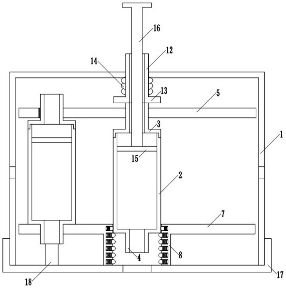
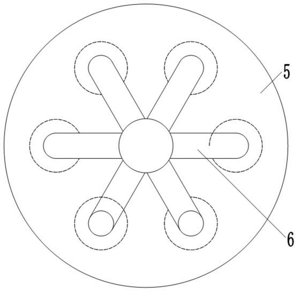
[0052] Such as figure 1 As shown, the embodiment of the present invention provides an art paint box for artistic design, comprising an outer shell 1, a plurality of paint tubes 2 are arranged inside the outer shell 1, and the upper end of each paint tube 2 is provided with a wall communicating with the inside. Feed pipe 3, the lower end of each paint tube 2 is also fixed with a discharge pipe 4 communicating with its inside; the diameters of the feed pipe 3 and the discharge pipe 4 are smaller than the diameter of the paint tube 2; the outer shell 1 Inside is provided with a support assembly for supporting the paint tube 2, the support assembly includes an upper disk 5, a lower disk 7 and a connecting assembly, the center of the upper disk 5 is provided with a through hole with a diameter greater than that of the paint tube 2, and the upper circle The disk 5 is provided with a chute 6 which is evenly distributed in the circumferential direction and communicates with the inside...
Embodiment 2
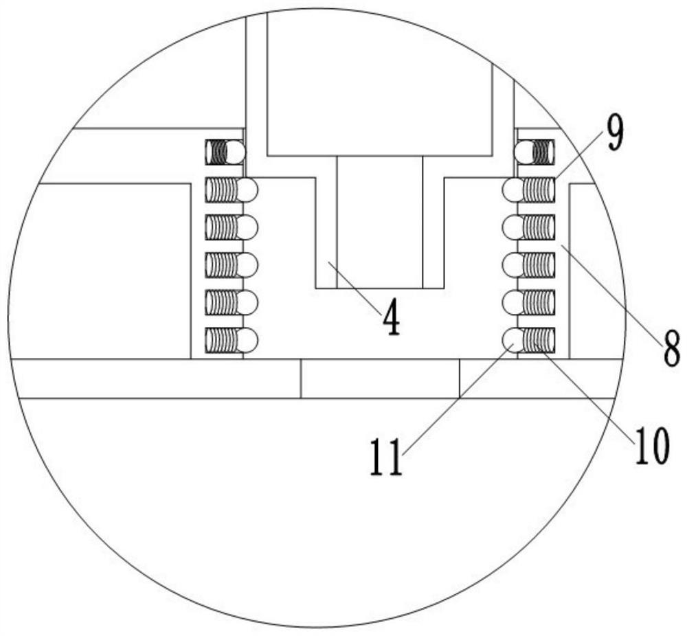
[0055] This embodiment is based on Embodiment 1. The buffer mechanism includes a plurality of buffer units, and the plurality of buffer units are evenly distributed on the side wall of the first cylinder 8 in the circumferential direction in multiple rows and rows, and each buffer unit includes a groove. 9. The first spring 10 and the steel ball 11, the groove 9 is set on the side wall of the first cylinder 8, the first spring 10 is arranged inside the groove 9, and one end of the first spring 10 is fixedly connected with the groove 9, The other end of the first spring 10 is fixedly connected with the steel ball 11, and when the first spring 10 is at the maximum extension distance, half of the steel ball 11 is located inside the groove 9, and half is located inside the first cylinder 8.
[0056] In the present invention, a plurality of buffer units are arranged in multiple rows and columns, and are evenly distributed on the side wall of the first cylinder 8 in the circumferenti...
Embodiment 3
[0058] This embodiment is based on Embodiment 2, the primary propulsion mechanism includes a second cylinder 12, the second cylinder 12 runs through the through hole provided on the outer casing 1 longitudinally, and the lower end of the second cylinder 12 is fixed with a push plate 13. A second spring 14 is sheathed on the outside of the second cylinder 12, the upper end of the second spring 14 is fixedly connected to the outer casing 1, and the lower end of the second spring 14 is fixedly connected to the push plate 13; Press the second cylinder 12, the second cylinder 12 pushes the push plate 13 to move downwards to contact the feed pipe 3, and the push plate 13 continues to move downwards to drive the paint tube 2 to pass through the buffer mechanism, Simultaneously, the discharge pipe 4 slides out from the through hole provided on the outer casing 1 .
[0059] Further, the secondary propulsion mechanism includes a piston 15 and a second pusher 16; the piston 15 is located...
PUM
 Abstract
Description
Claims
Application Information
 - R&D
- Intellectual Property
- Life Sciences
- Materials
- Tech Scout
- Unparalleled Data Quality
- Higher Quality Content
- 60% Fewer Hallucinations
Browse by: Latest US Patents, China's latest patents, Technical Efficacy Thesaurus, Application Domain, Technology Topic, Popular Technical Reports.
© 2025 PatSnap. All rights reserved.Legal|Privacy policy|Modern Slavery Act Transparency Statement|Sitemap|About US| Contact US: help@patsnap.com


