Hub tightening device capable of being adjusted according to hub diameter

A wheel hub and adjusting cavity technology, applied in tire installation, wheel assembly and disassembly equipment, wheels, etc., can solve problems such as increased wheel rotational friction, reduced car sliding performance, inability to tighten wheel hubs, etc., to improve work efficiency and efficiency. and quality effects

Active Publication Date: 2021-05-07
临沂市通佳工程机械有限公司
View PDF6 Cites 0 Cited by
  • Summary
  • Abstract
  • Description
  • Claims
  • Application Information

AI Technical Summary

Problems solved by technology

[0002] Car maintenance refers to the process of carrying out a new maintenance and care process for the car by using special care materials and products of different properties according to the maintenance conditions required by different materials in various parts of the vehicle; the maintenance of tires in the driving system is also a kind of car maintenance. Whether the tightness of the wheel bearing in the driving system of the car is appropriate will seriously affect the sliding performance of the car. If the wheel hub bearing is too tight, it will increase the friction of the wheel rotation; if it is too loose, the wheel will easily skew or shake during driving, increasing The friction between the wheel and the ground reduces the sliding performance of the car, and the tightness of the car tires is generally controlled manually, and there is a certain degree of uncertainty in the manual operation of the wheel hub tightness, which leads to the failure of the ideal wheel hub tightness. State; the general wheel hub tensioning device generally cannot tighten the wheel hub after changing the diameter, so it is necessary to design a wheel hub tightening device that can be adjusted according to the wheel hub diameter

Method used


Image

  • Hub tightening device capable of being adjusted according to hub diameter
  • Hub tightening device capable of being adjusted according to hub diameter
  • Hub tightening device capable of being adjusted according to hub diameter

Examples


Embodiment Construction

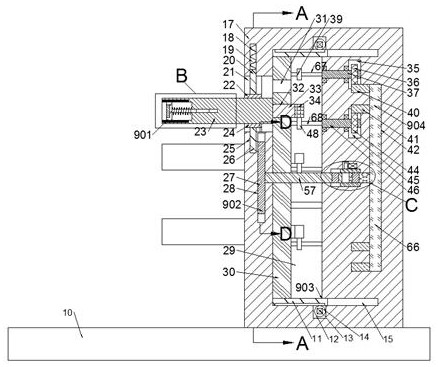
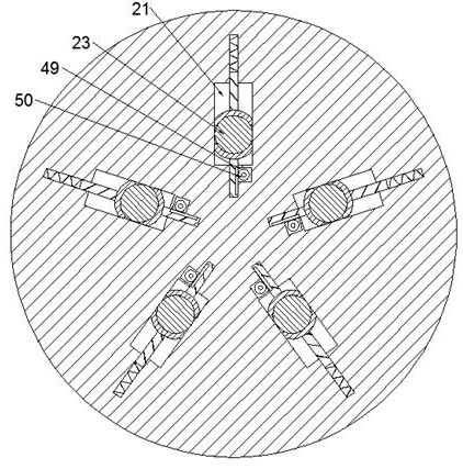
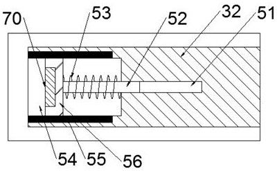
[0017] Combine below Figure 1-5 The present invention is described in detail, and for convenience of description, the orientations mentioned below are now stipulated as follows: figure 1 The up, down, left, right, front and back directions of the projection relationship itself are the same.

[0018] refer to Figure 1-5 According to an embodiment of the present invention, a hub tightening device that can be adjusted according to the diameter of the hub includes a base 10, and the upper side of the base 10 is provided with a working box 17 that can be electrically controlled to slide left and right, and the left side of the working box 17 is The side wall body is provided with a tightening device 901 for tightening the tire thread. The tightening device 901 includes a sliding chamber 29 arranged in the working box 17, and the working box on the right side of the sliding chamber 29 is 17 is provided with a sliding chamber two 59, and the upper side wall of the sliding chamber...


PUM


Abstract

The invention discloses a hub tightening device capable of being adjusted according to the hub diameter, the device comprises a machine body, a working box capable of being electrically controlled to slide left and right is arranged on the upper side of a base, a tightening device body used for tightening tire threads is arranged in the left side wall body of the working box, and the tightening device body comprises a first sliding cavity formed in the working box; a second sliding cavity is formed in the position, on the right side of the first sliding cavity, in the working box. The device has the beneficial effects that the device is provided with the tightening device, automatic tightening operation on an automobile tire can be achieved through tightening transmission of a tightening arm, and therefore the working efficiency is greatly improved; the adjusting device is arranged, the position can be adjusted by driving the tightening arms arranged in an array, so that screws of automobile tires with different diameters can be tightened, manual tightening operation on the automobile tires can be replaced by machinery, and the screw mounting efficiency and quality of the automobile tires are greatly improved.

Description

technical field [0001] The invention relates to the technical field related to automobile maintenance, in particular to a wheel hub tightening device that can be adjusted according to the diameter of the wheel hub. Background technique [0002] Car maintenance refers to the process of carrying out a new maintenance and care process for the car by using special care materials and products of different properties according to the maintenance conditions required by different materials in various parts of the vehicle; the maintenance of tires in the driving system is also a kind of car maintenance. Whether the tightness of the wheel bearing in the driving system of the car is appropriate will seriously affect the sliding performance of the car. If the wheel hub bearing is too tight, it will increase the friction of the wheel rotation; if it is too loose, the wheel will easily skew or shake during driving, increasing The friction between the wheel and the ground reduces the slidi...

Claims


Application Information

Patent Timeline
IPC IPC(8): B60B29/00B25B21/00
CPCB60B29/006B25B21/00
Inventor 李妍
Owner 临沂市通佳工程机械有限公司
Why Eureka
Try Eureka