Overhead, cable-free and high-load-bearing charging pile and intelligent parking system

A charging pile, high-load-bearing technology, applied in the field of charging piles and intelligent parking systems, can solve the problems of shortened service life, inconsistent thread pressure, thick charging cable, etc., and achieves improved service life, good locking effect, and smooth push. Effect

Pending Publication Date: 2021-05-07
JIANGMEN RUNSHENG ELECTROMECHANICAL CO LTD
View PDF9 Cites 0 Cited by
  • Summary
  • Abstract
  • Description
  • Claims
  • Application Information

AI Technical Summary

Problems solved by technology

[0003] In this case, it realizes the four-section synchronous lifting through the first hollow screw and the second hollow screw, but the problem with this solution is that in the case of high load, the pressure is directly transmitted from the screw to the screw , as the first hollow screw goes deeper into the second hollow screw, its thread contact surface becomes larger and larger, and as the first hollow screw withdraws from the second hollow screw, its thread contact surface becomes smaller and smaller, However, the bearing ca

Method used


Image

  • Overhead, cable-free and high-load-bearing charging pile and intelligent parking system
  • Overhead, cable-free and high-load-bearing charging pile and intelligent parking system
  • Overhead, cable-free and high-load-bearing charging pile and intelligent parking system

Examples


Embodiment 1

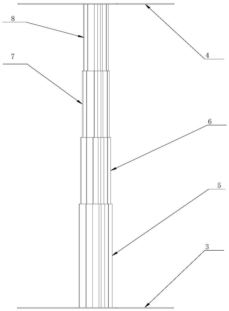
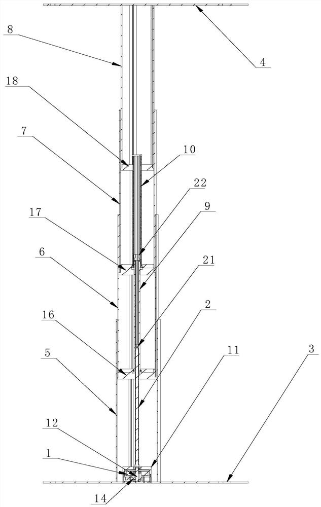
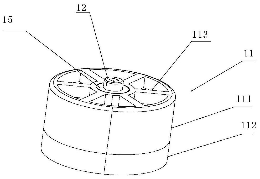
[0057] see Figure 1-9 , an overhead, cable-free, high-load charging pile, including a motor 1, a first screw rod 2; a first fixing plate 3, a second fixing plate 4, a first sleeve 5, a second sleeve 6, The third sleeve 7, the fourth sleeve 8, the second screw mandrel 9, the third screw mandrel 10, the motor box 11 is fixed on the first fixing plate 3, and the motor 1 is fixed in the motor box 11 , the bottom of the first screw mandrel 2 is coaxially fixedly connected with a driving rod 12, and the driving rod 12 is connected to the motor 1 in transmission, and the driving rod 12 is provided with a locking part 13, and the motor box 11 is provided with There is a locking fitting part 14 that cooperates with the locking part 13; the upper surface of the driving rod 12 and the motor box 11 is connected by a plane thrust bearing 15;

[0058] The first sleeve 5, the second sleeve 6, the third sleeve 7, and the fourth sleeve 8 are sequentially socketed from bottom to top, the firs...

Embodiment 2

[0088] It is substantially the same as Embodiment 1, except that the conductive member is implemented in another form. Specifically, the conductive member includes the outer walls of the second sleeve 6, the third sleeve 7, and the fourth sleeve 8. The first conductive strip 41 and the second conductive strip 42 arranged on the inner walls of the first sleeve 5, the second sleeve 6, and the third sleeve 7, the second conductive strip 42 of the first sleeve 5 and the second sleeve The first conductive strip 41 of the sleeve 6 is electrically connected, the second conductive strip 42 of the second sleeve 6 is electrically connected with the first conductive strip 41 of the third sleeve 7, and the second conductive strip 42 of the third sleeve 7 is electrically connected to the first conductive strip 41 of the third sleeve 7. The first conductive strip 41 of the four sleeves 8 is electrically connected, the second conductive strip 42 of the first sleeve 5 is electrically connected...

Embodiment 3

[0093] refer to Figure 11 and Figure 12 , an intelligent parking system, comprising a parking space 100, a controller 200, a pair of charging piles 300 described in Embodiment 1 arranged on both sides of the entrance of the parking space 100, a remote server 400, and an APP 500;

[0094] A display screen 600 is fixed between the two second fixing plates, and the display screen 600 is electrically connected to the conductive member; the first fixing plate is fixed on the top of the top wall of the parking space.

[0095] The remote server 400 is communicated with the controller 200, and the user sends a control command to the remote server 400 by logging into the APP 500 to perform payment operations;

[0096] The charging interface is connected with a charging gun 700 for charging the electric vehicle;

[0097] The motor, the display screen 600 and the charging gun 700 are electrically connected to the controller 200 .

[0098] The parking system of the present invention ...


PUM


Abstract

The invention belongs to the field of intelligent parking, and discloses an overhead, cable-free and high-load-bearing charging pile which comprises a motor and a first lead screw. The system further comprises a first fixing plate, a second fixing plate, a first sleeve, a second sleeve, a third sleeve, a fourth sleeve, a second lead screw and a third lead screw, a motor box is fixed to the first fixing plate, the motor is fixed in the motor box, and the first sleeve, the second sleeve, the third sleeve and the fourth sleeve are electrically connected through conductive parts. One end of each conductive part is connected with the charging interface, the other end of the conductive part is connected with a power supply interface, the charging pile is characterized in that the charging pile is realized based on an electric push rod, the electric push rod has the characteristics of multiple sections capable of synchronously lifting to realize stable pushing of an overweight object (generally greater than 500kg), and meanwhile, the conductive electric push rod is free of a wire and the charging operation of the electric vehicle is realized. The invention further discloses an intelligent parking system.

Description

technical field [0001] The invention relates to the field of intelligent parking, in particular to an overhead, cable-free, high-load charging pile and an intelligent parking system. Background technique [0002] CN201720658761.5 discloses a four-section stroke synchronous lifting electric push rod, which includes a push rod outer cylinder and a motor arranged in the bottom of the outer cylinder. The lower end of the sleeve is movably connected with a first screw seat, a first inner cylinder is provided between the first screw seat and the outer cylinder, the upper end of the sleeve is fixedly connected with a first hollow screw, and the first hollow screw The upper thread is connected with a second hollow screw, and the second hollow screw is connected to the top cover of the push rod through the threaded connection of the outer tube of the top cover. It has a four-section extension stroke, simple and compact design, and can realize simultaneous lifting of four-section str...

Claims


Application Information

Patent Timeline
IPC IPC(8): B60L53/31B60L53/16B60L53/66E04H6/42
CPCB60L53/16B60L53/31B60L53/665E04H6/42Y02T10/70Y02T10/7072Y02T90/12Y02T90/14Y02T90/16
Inventor 黄正滨
Owner JIANGMEN RUNSHENG ELECTROMECHANICAL CO LTD
Why Eureka
Try Eureka