

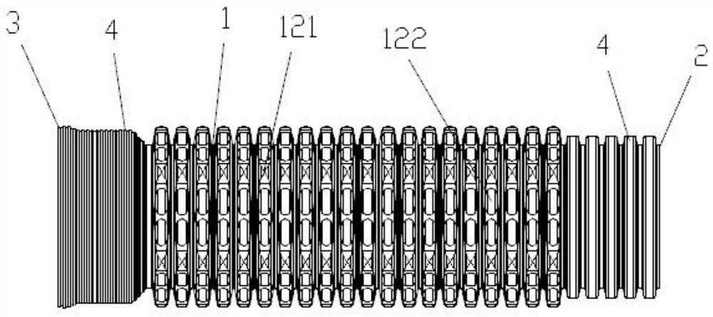
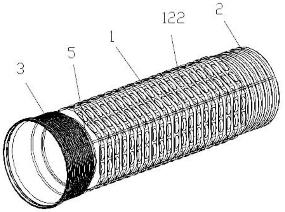
Outer polygonal impeller-shaped reinforced composite pipe
A technology for enhancing composite and polygonal waves, applied in the direction of hoses, pipes, piping systems, etc., can solve the problems of safety, weak uniformity of force on the full polygonal outer wall structure, difficult installation of durability, and reduced flexibility of pipes, etc. Good effect of hindering soil and water loss, avoiding improper installation and large expansion area
- Summary
- Abstract
- Description
- Claims
- Application Information
AI Technical Summary
Problems solved by technology
Method used
Image

Examples
Embodiment Construction
[0019] The following will clearly and completely describe the technical solutions in the embodiments of the present invention with reference to the accompanying drawings in the embodiments of the present invention. Obviously, the described embodiments are only some, not all, embodiments of the present invention.
[0020] It should be noted that when a component / feature is referred to as being “disposed on” another component / part, it can be directly disposed on the other component / part or an intervening component / part may also be present. When a component / part is referred to as being "connected / coupled" to another component / part, it can be directly connected / coupled to the other component / part or intervening parts / parts may also be present. As used herein, the term "connected / coupled" may include electrical and / or mechanical physical connections / coupled. As used herein, the term "comprising / comprising" refers to the presence of a feature, step or component / part, but does not ex...
PUM
 Abstract
Description
Claims
Application Information