
External gear-shaped reinforced composite pipe

An enhanced compound, gear-shaped technology, applied in the direction of hoses, pipes, pipeline systems, etc., can solve the problems of safety, weak uniformity of force on the full polygonal outer wall structure, difficult installation of durability, and reduced flexibility of pipelines, etc. Good effect of hindering soil and water loss, avoiding improper installation and large expansion area

Pending Publication Date: 2021-05-07
GUANGDONG YONGGAO PLASTIC INDUSTRY DEVELOPMENT CO LTD
View PDF1 Cites 2 Cited by
  • Summary
  • Abstract
  • Description
  • Claims
  • Application Information

AI Technical Summary

Problems solved by technology

It was first successfully developed in Germany in the early 1980s. After more than ten years of development and improvement, the promotion and application of double-wall corrugated pipes are on the rise. There are installation difficulties and safety hazards in installation and durability
[0003] In order to solve the above problems, the patent number: CN201720489818.3 proposes an outer octagonal inner circle double-wall bellows, the inner wall of which is a double-wall bellows with a cylindrical structure, which changes the outer wall of the conventional ring structure into a polygon structure to increase the contact area between the outer surface of the pipeline and the foundation in order to solve the above-mentioned problems, but the full polygon outer wall bellows structure proposed in this patent will cause the flexibility of the pipeline to decrease compared with the outer wall bellows of the ring structure. It cannot solve the safety problem, and the force uniformity of the full polygonal outer wall structure will be relatively weak

Method used


Image

  • External gear-shaped reinforced composite pipe
  • External gear-shaped reinforced composite pipe
  • External gear-shaped reinforced composite pipe

Examples


Embodiment Construction

[0017] The following will clearly and completely describe the technical solutions in the embodiments of the present invention with reference to the accompanying drawings in the embodiments of the present invention. Obviously, the described embodiments are only some, not all, embodiments of the present invention.

[0018] It should be noted that when a component / feature is referred to as being “disposed on” another component / part, it can be directly disposed on the other component / part or an intervening component / part may also be present. When a component / part is referred to as being "connected / coupled" to another component / part, it can be directly connected / coupled to the other component / part or intervening parts / parts may also be present. As used herein, the term "connected / coupled" may include electrical and / or mechanical physical connections / coupled. As used herein, the term "comprising / comprising" refers to the presence of a feature, step or component / part, but does not ex...


PUM


Abstract

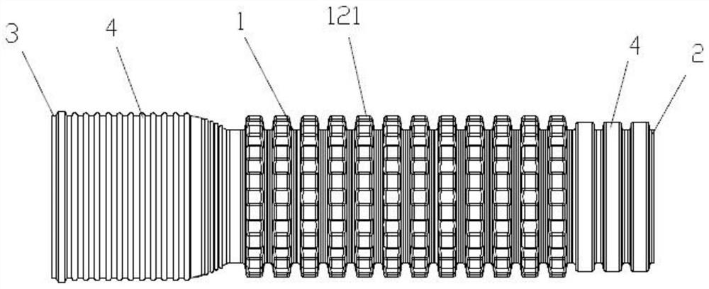
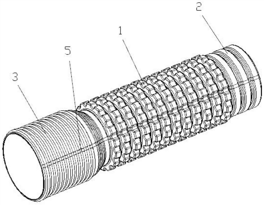
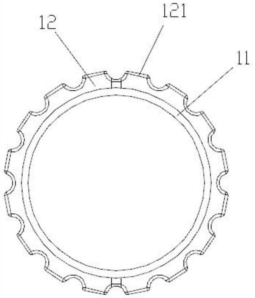
The invention provides an external gear-shaped reinforced composite pipe. The external gear-shaped reinforced composite pipe is characterized in that the external gear-shaped reinforced composite pipe comprises a pipe body, a spigot and a socket, wherein the spigot and the socket are arranged at the two ends of the pipe body respectively, the pipe body comprises an inner layer and an outer layer, the cross section of the inner layer is in a circular ring shape, the outer layer comprises a plurality of gear-shaped circular ring protrusions, and the gear-shaped circular ring protrusions are of hollow structures; and the cross section of the outer layer is in a gear ring shape, and the cross section of the spigot and the cross section of the socket are both in a ring shape. According to the external gear-shaped reinforced composite pipe, the outer layer of the pipe body is of a gear circular ring structure, the contact area of the pipe body and soil can be enlarged, good anti-sedimentation capacity is achieved, water and soil loss is prevented, higher rigidity and higher load resistance are achieved, the axial flexibility of traditional double-wall corrugations is reserved, stress is uniform, and collapse caused by local buckling deformation or reverse bending deformation is not liable to occur.

Description

technical field [0001] The invention relates to the technical field of plastic pipes, in particular to an external gear-shaped reinforced composite pipe. Background technique [0002] Double-wall plastic corrugated pipe has a ring-shaped outer wall and a smooth cylindrical inner wall. With its excellent performance, it is widely used in buried drainage pipes, etc. It was first successfully developed in Germany in the early 1980s. After more than ten years of development and improvement, the promotion and application of double-wall corrugated pipes are on the rise. There are installation difficulties and safety hazards in terms of installation and durability. [0003] In order to solve the above problems, the patent number: CN201720489818.3 proposes an outer octagonal inner circle double-wall bellows, the inner wall of which is a double-wall bellows with a cylindrical structure, which changes the outer wall of the conventional ring structure into a polygon structure to incr...

Claims


Application Information

Patent Timeline
Patent Type & Authority Applications(China)
IPC IPC(8): F16L11/118F16L11/15F16L33/18F16L47/06F17D5/00
CPCF16L11/118F16L11/15F16L33/18F16L47/065F17D5/00
Inventor 张炜黄米财王秋腾卢康成
Owner GUANGDONG YONGGAO PLASTIC INDUSTRY DEVELOPMENT CO LTD
Learn More