A leaky-wave antenna with high scan rate based on metamaterial elements

A technology of leaky wave antenna and scanning rate, which is applied in the direction of slot antenna, antenna grounding switch structure connection, radiation element structure form, etc., can solve the problems such as difficult to use the pre-stage circuit, achieve feeding and impedance matching, and have great application prospects Effect

Active Publication Date: 2022-07-29
HANGZHOU DIANZI UNIV
View PDF8 Cites 0 Cited by
  • Summary
  • Abstract
  • Description
  • Claims
  • Application Information

AI Technical Summary

Problems solved by technology

Among them, the narrow band will greatly simplify the requirements of the front-end hardware, while the traditional leaky wave antenna usually requires several gigabits of bandwidth, and it is usually difficult to use the traditional front-end circuit

Method used


Image

  • A leaky-wave antenna with high scan rate based on metamaterial elements
  • A leaky-wave antenna with high scan rate based on metamaterial elements
  • A leaky-wave antenna with high scan rate based on metamaterial elements

Examples


Embodiment 1

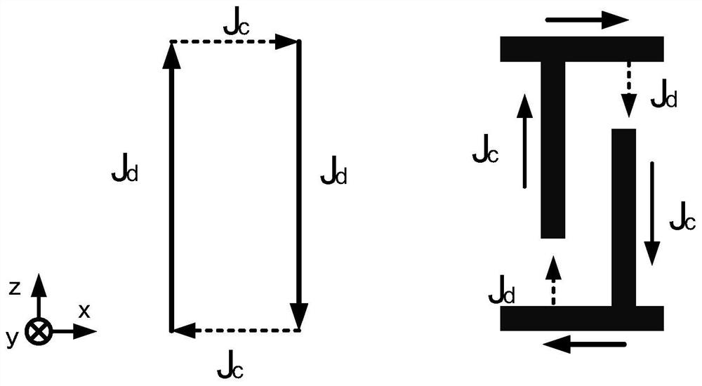
[0025] like figure 1 As shown, the complementary L-shaped metal resonant structure of the leaky wave antenna with high scanning rate adopted in the present invention is composed of two L-shaped metal strips placed in parallel. When an electromagnetic wave passes through, the induced current in the metal sheet becomes the conductive current Jc (the conductive current), and there is a capacitance between the two metal strips, so a displacement current Jd (the displacement current Jd (the displacement current) is generated between the head and the tail of the two metal strips). ), thus forming a current loop and generating resonance. The resonance produces an equivalent negative permittivity and an equivalent negative permeability around the metal structure, making the medium appear as a left-handed material with double negative properties.

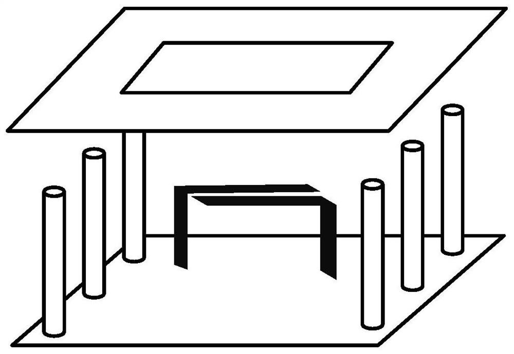
[0026] like figure 2 As shown, the unit structure of the leaky wave antenna is composed of the SIW integrated substrate waveguide, the m...


PUM


Abstract

The invention discloses a leaky wave antenna with high scanning rate based on metamaterials. The antenna is loaded with a complementary L-shaped subwavelength metal resonance unit to realize left-handed electromagnetic characteristics of a specific frequency band. The antenna unit includes a pair of complementary L-shaped metal resonator units, which are composed of metal vias and printed metal strips, and the top layer corresponding to the position of the metal resonator is slotted in a rectangle to achieve electromagnetic wave leakage. The period p of the antenna element satisfies the space harmonic formula of the periodic leaky-wave antenna: β n= β 0 -2 π n / p . The leaky wave antenna adopts SIW structure, and the trapezoidal SIW structure and microstrip line are used at the port to realize port feeding and impedance matching. The antenna adopts SIW structure and microstrip feed, small size, stable structure and high scanning rate of the pattern in the unit frequency band, which has high practical potential for applications such as communication engineering, microwave imaging and radar scanning.

Description

technical field [0001] The invention belongs to the technical field of wireless communication, and relates to a leaky wave antenna with a high directional pattern scan rate based on a metamaterial structure utilizing a metal subwavelength unit. Background technique [0002] The leaky wave antenna is a typical traveling wave antenna, which has the characteristics of wide bandwidth, narrow beam width and beam scanning, and its feeding method is simple and the manufacturing cost is low. Leaky-wave antennas have potential information transmission applications in time-frequency conversion due to their ability to change the beam scanning direction with frequency. According to this characteristic, leaky wave antenna has potential application value in radar, microwave imaging, spectrum analysis and communication engineering. [0003] The leaky wave antenna originated from a continuous long straight slot in the side wall of the metal waveguide along the propagation direction, and la...

Claims


Application Information

Patent Timeline
Patent Type & Authority Patents(China)
IPC IPC(8): H01Q1/38H01Q1/50H01Q13/10
CPCH01Q1/38H01Q1/50H01Q13/10
Inventor 徐魁文王权段江波彭亮
Owner HANGZHOU DIANZI UNIV
Why Eureka
Try Eureka