
Balanced momentum probe holder

a technology of momentum probes and holder plates, applied in the direction of mechanical measuring arrangements, mechanical roughness/irregularity measurements, instruments, etc., can solve the problems of insufficient ability in present-day devices, actuator movement is relatively slow, and the inability to accurately characterize a sample surface is often limited, so as to achieve the effect of reducing or eliminating parasitic oscillations

Inactive Publication Date: 2006-03-02
BRUKER NANO INC
View PDF15 Cites 5 Cited by
  • Summary
  • Abstract
  • Description
  • Claims
  • Application Information

AI Technical Summary

Benefits of technology

[0014] It is an object of the present invention to provide a novel balanced momentum probe holder for scanning probe microscopes and / or stylus profilers that permits the probe to measure the height of small surface features better than is presently possible with commercially available tools. It is specifically an object to provide such a probe holder for an improved atomic force microscope (AFM).
[0015] Another object of the present invention is to provide a novel AFM that permits more accurate imaging of surface features at high scan rates.
[0016] Still another object of this invention is to provide an AFM that can measure surface features at high scan rates without inducing parasitic oscillations in the AFM.

Problems solved by technology

In analyzing biological samples, polymers, photoresist, metals and insulators, thin films, silicon wafer surfaces, and other surfaces, the ability to accurately characterize a sample surface is often limited by the present ability of an AFM to move the stylus vertically relative to the surface at a rate sufficient to accurately measure the surface while scanning in either the X or Y direction.
This ability is inadequate in present day devices for essentially two reasons.
Unfortunately, a necessary by-product of a larger Z actuator having greater range is associated greater mass which makes the actuator movement relatively slow.
Slow actuators are not able to move the probe rapidly enough in Z while scanning in X or Y at anything more than modest speed without damaging the probe or sample or without sacrificing measurement accuracy.
Because it is important while scanning to minimize the force of the stylus on the sample to prevent damage to the stylus and / or sample, the scan rate in X or Y must, of necessity, be reduced to a speed compatible with the Z actuator's ability to move the stylus up and over surface features without slamming into them, which is obviously undesirable.
This works only to a limited degree because if the gain is increased more than a modest amount, the Z actuator begins to resonate and that resonance is passed into the AFM, creating parasitic oscillations, which in turn ruin image quality.
In essence, a large mass, large displacement Z actuator cannot be made to overcome its inherent physical limitations.
Unfortunately, at high gain, the high speed of operation and momentum of the fast Z actuator can similarly cause parasitic oscillations which reduce image quality.

Method used


Image

  • Balanced momentum probe holder
  • Balanced momentum probe holder
  • Balanced momentum probe holder

Examples


Embodiment Construction

[0038] As suggested above, sample surfaces may be characterized by using probe-based instruments such as scanning probe microscopes, stylus profilers, or any other instrument capable of obtaining, recording, and manipulating sample surface information. While all of these applications are within the scope of the present invention, the preferred embodiment describes the invention as included in an Atomic Force Microscope (AFM) but does not exclude other SPMs.

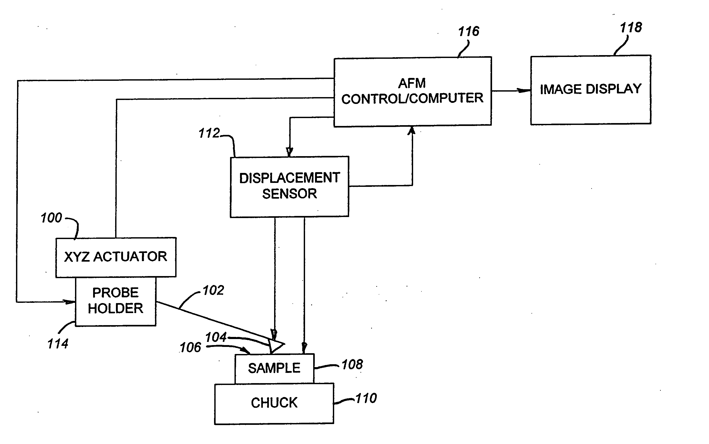
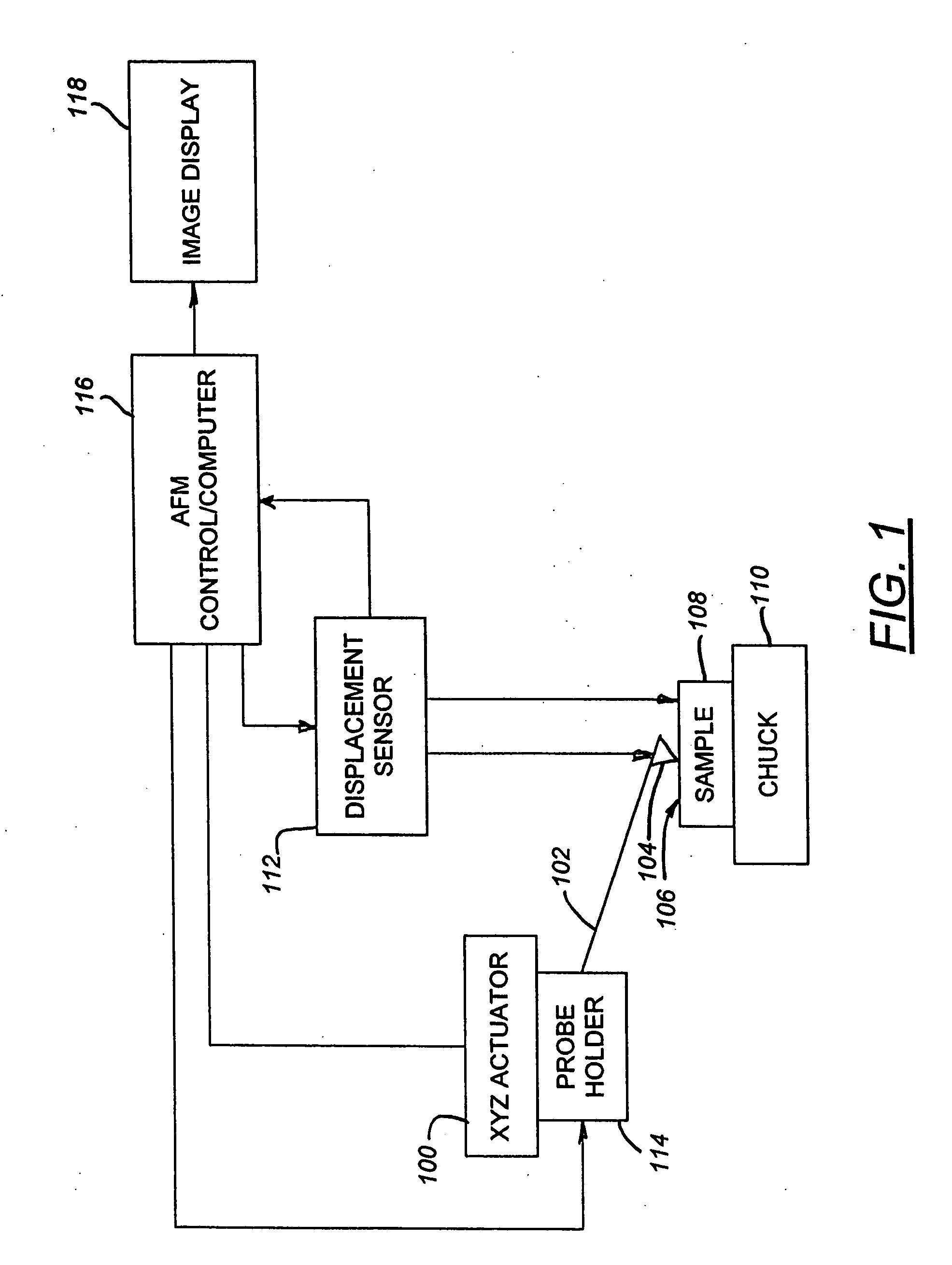
[0039] An AFM-based system which incorporates the balanced momentum probe holder of the present invention and which is capable of acquiring sample surface data, recording the surface data, and manipulating the data to perform desired tasks is schematically illustrated in FIG. 1.

[0040] The AFM-based system (FIG. 1) includes an XYZ actuator 100 to which a cantilever arm 102 is operatively connected. A stylus 104 is mounted on the other end of the cantilever 102 for characterizing a surface 106 of a sample 108 releasably affixed to...


PUM

PropertyMeasurementUnit
momentumaaaaaaaaaa
massaaaaaaaaaa
frequencyaaaaaaaaaa

Abstract

A balanced momentum probe holder in an apparatus for characterizing a sample surface has first and second members each having extensible and retractable distal ends. The distal ends extend or retract substantially simultaneously in response to a signal from a detector thus balancing the momentums of the first and second members and reducing the net momentum of the probe holder to essentially zero. Balancing the momentum of the probe holder reduces parasitic oscillations in the apparatus thus enhancing performance.

Description

RELATED APPLICATION [0001] The present application is a continuation application of U.S. patent application Ser. No. 10 / 614,425, filed Jul. 7, 2003, entitled, “BALANCED MOMENTUM PROBE HOLDER,” which is a continuation of U.S. patent application Ser. No. 09 / 766,555, filed Jan. 19, 2001, entitled, “BALANCED MOMENTUM PROBE HOLDER,” the disclosures of which are incorporated herein in their entirety.FIELD OF THE INVENTION [0002] The present invention is generally directed to a balanced momentum probe holder for use in metrology systems, especially scanning probe microscopes used to measure sample surfaces down to the nanometer level. Specifically, the invention is directed to such systems employing nested-Z and non-nested parallel feedback loops, to achieve rapid, and highly accurate scanning of a sample surface. The invention also relates to methods of using such a probe holder in such systems. BACKGROUND OF THE INVENTION [0003] The ongoing miniaturization of components of a variety of d...

Claims


Application Information

Patent Timeline
Patent Type & Authority Applications(United States)
IPC IPC(8): G12B21/24G01N13/16G01Q10/00G01B21/00G01Q10/04G01Q10/06G01Q60/24G01Q70/00G01Q70/02G01Q70/04
CPCB82Y35/00G01Q10/04G01Q70/04G01Q70/02G01Q10/06
Inventor MASSIE, JAMES R.
Owner BRUKER NANO INC
Learn More