Dynamic optical devices

a technology of optical devices and dynamic optical components, applied in the direction of optical elements, multiplex communication, instruments, etc., can solve the problems of system bulky and space-consuming, low efficiency, and strict limitation of the number of possible channels, and achieve the effect of high scanning ra

Inactive Publication Date: 2009-12-17
BEAMUS
View PDF10 Cites 3 Cited by
  • Summary
  • Abstract
  • Description
  • Claims
  • Application Information

AI Technical Summary

Benefits of technology

[0007]It is therefore a broad object of the present invention to provide a compact, relatively inexpensive, accurate and simple beam steering optical device having a high scanning rate.
[0008]It is a further object of the invention to provide a compact, relatively inexpensive, accurate and simple optical device for wavelength division multiplexion / demultiplexion having high spectral separation.

Problems solved by technology

These proposed systems generally suffer from low efficiencies, or from a strict limitation on the number of possible channels.
However, the necessity to use a conventional aspheric lens for collimating and / or focusing the light waves makes such systems bulky and space consuming.
These systems suffer from various drawbacks: the scanning unit is relatively large and heavy, limiting the performance of systems in which compactness is a requirement; mass production is quite expensive; the scanning rate is severely limited by the mechanical system; rotating systems usually suffer from wobble which must be restrained in order to allow accurate scanning.
These approaches usually suffer from high aberrations at small f-numbers.
In addition, they must rely on fairly complicated and costly equipment, which often limits the performance of the microlens arrays.

Method used


Image

  • Dynamic optical devices
  • Dynamic optical devices
  • Dynamic optical devices

Examples


Embodiment Construction

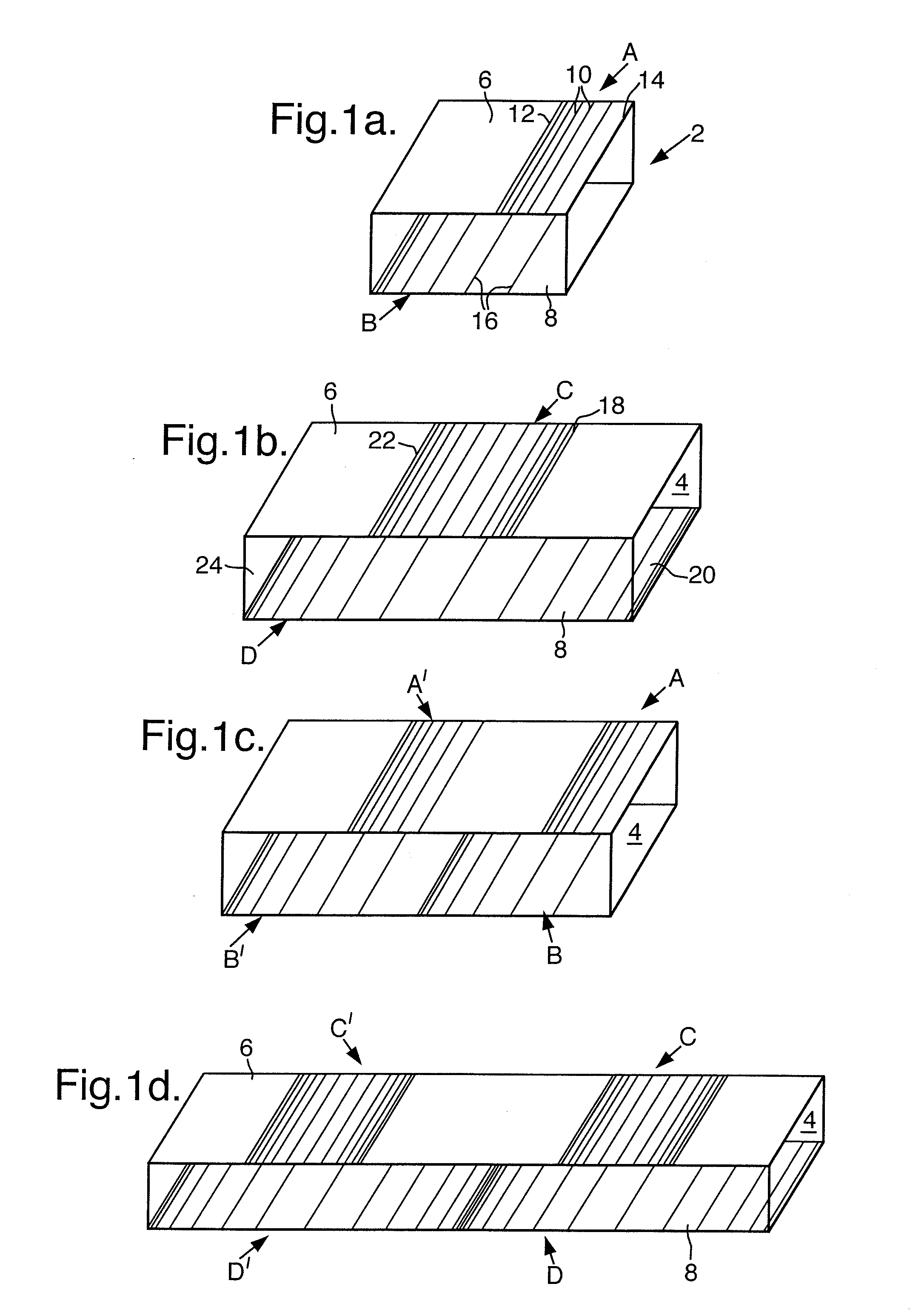
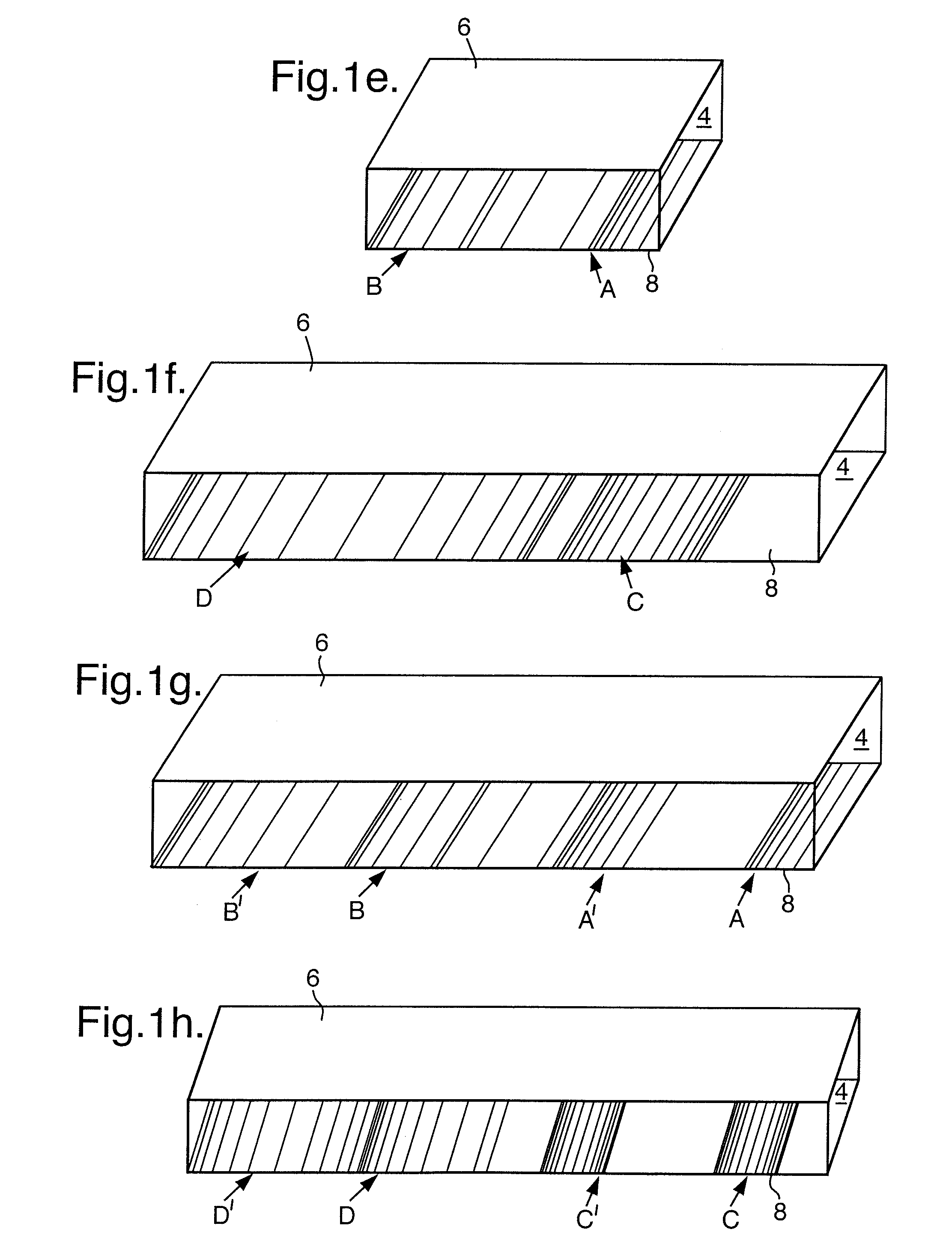
[0032]In its simplest form, as shown in FIG. 1a, the optical device 2 of the present invention includes a light-transmissive substrate 4 having two facets or surfaces 6, 8. A plurality of parallel lines 10 are made on surface 6, constituting a first grating A. The spacings between the lines increase from one edge 12 of the surface to its other edge 14, according to mathematical formulae. The arrangement of lines 16 on surface 8 forms a second grating B. The spacings between the parallel lines 16 of second grating B increase in the same direction as those of grating A.

[0033]According to the embodiment of FIG. 1b, the surfaces 6 and 8, respectively, bear gratings C and D, each grating being formed of parallel lines, the spacings of which increase from one edge 18 and 20, respectively, of the surfaces to their centers, and then decrease towards the other respective edge 22, 24, in a symmetrical manner.

[0034]FIG. 1c depicts a modification of the arrangement of FIG. 1b, wherein the subst...


PUM

PropertyMeasurementUnit
wavelengthsaaaaaaaaaa
constant distanceaaaaaaaaaa
distanceaaaaaaaaaa

Abstract

The invention provides an optical device, including a light-transmissive substrate, and a pair of different, parallel gratings including a first grating and second grating, located on the substrate at a constant distance from each other, each of the pair of parallel gratings including at least one sequence of a plurality of parallel lines, wherein the spacings between the lines gradually increase from one edge of the grating up to a maximum distance between the lines, and wherein the arrangement of lines in the second grating is in the same direction as that of the first grating. A system utilizing a plurality of such optical devices is also disclosed.

Description

FIELD OF THE INVENTION [0001]The present invention relates to diffractive optical devices (DOEs), and to devices which include a plurality of chirped diffractive optical elements carried by a common light-transmissive substrate.[0002]The present invention is capable of being implemented in a large member of applications. For purposes of example only, implementations in division multiplexing / demultiplexing systems, compact optical switches and compact optical scanners are indicated herein.BACKGROUND OF THE INVENTION [0003]Recently, there have been significant advances in optical fiber technology for telecommunication systems. One of the proposed methods of exploiting the high potential bandwidth of optical fibers more efficiently, is by wavelength division multiplexing (WDM). With this technique, a large number of communication channels can be transmitted simultaneously over a single fiber. Various systems for implementing WM have been proposed, including systems based on birefringen...

Claims


Application Information

Patent Timeline
Patent Type & Authority Applications(United States)
IPC IPC(8): H04J14/00G02B5/18G02B6/34G02F1/035
CPCG02B5/1866G02F1/035G02B6/1203H04J14/02G02B6/29304G02F2201/305
Inventor AMITAI, YAAKOV
Owner BEAMUS
Why Eureka
Try Eureka