Method and device for determining the position of a mobile closing part of a vehicle

A technology for closures and automobiles, applied to measuring devices, vehicle components, transportation and packaging, etc., can solve problems such as large system costs

Inactive Publication Date: 2011-01-19
CONTINENTAL AUTOMOTIVE GMBH
View PDF11 Cites 6 Cited by
  • Summary
  • Abstract
  • Description
  • Claims
  • Application Information

AI Technical Summary

Problems solved by technology

This in turn requires the use of microcomputers with high computational efficiency, resulting in huge system costs

Method used


Image

  • Method and device for determining the position of a mobile closing part of a vehicle
  • Method and device for determining the position of a mobile closing part of a vehicle

Examples


Embodiment Construction

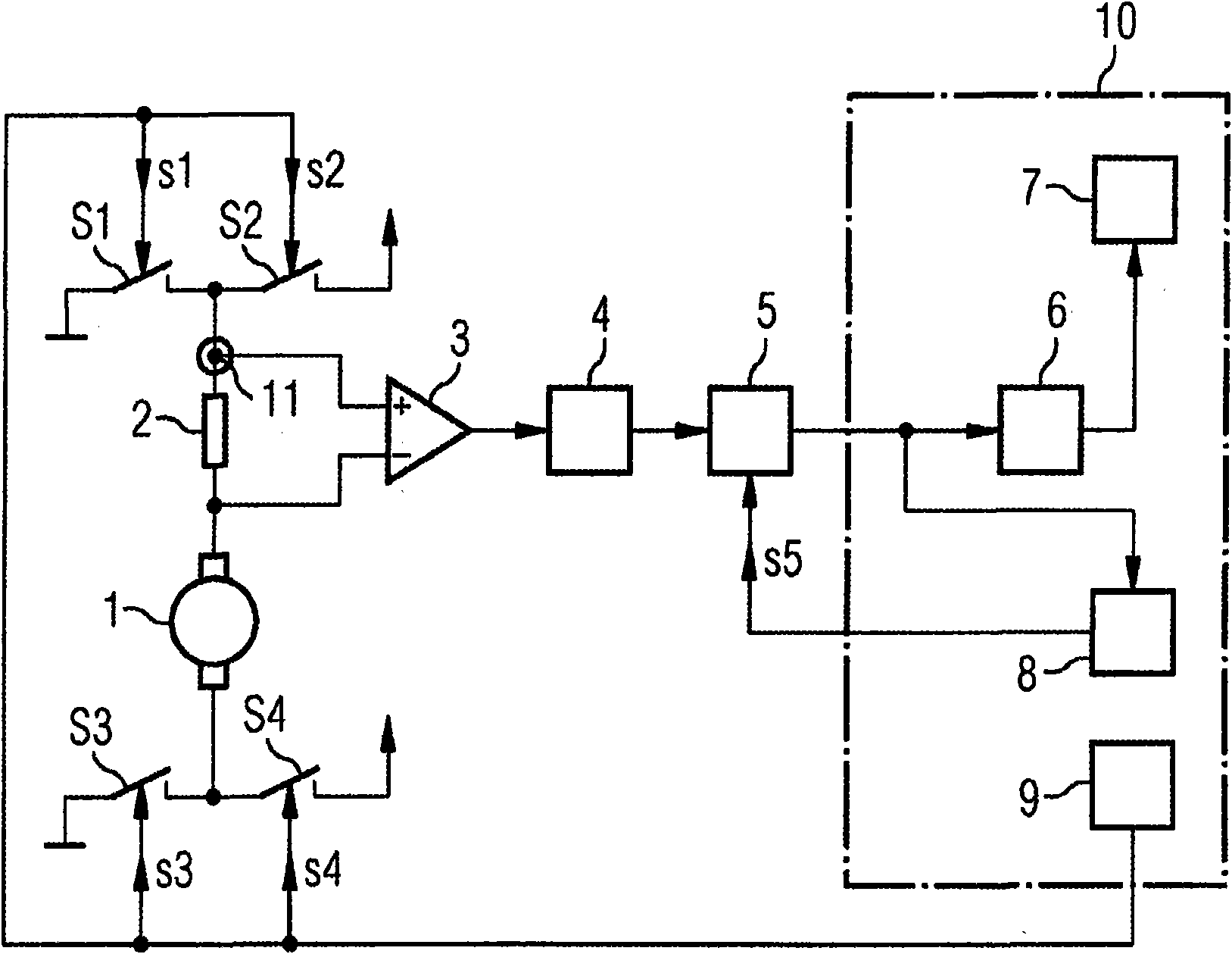
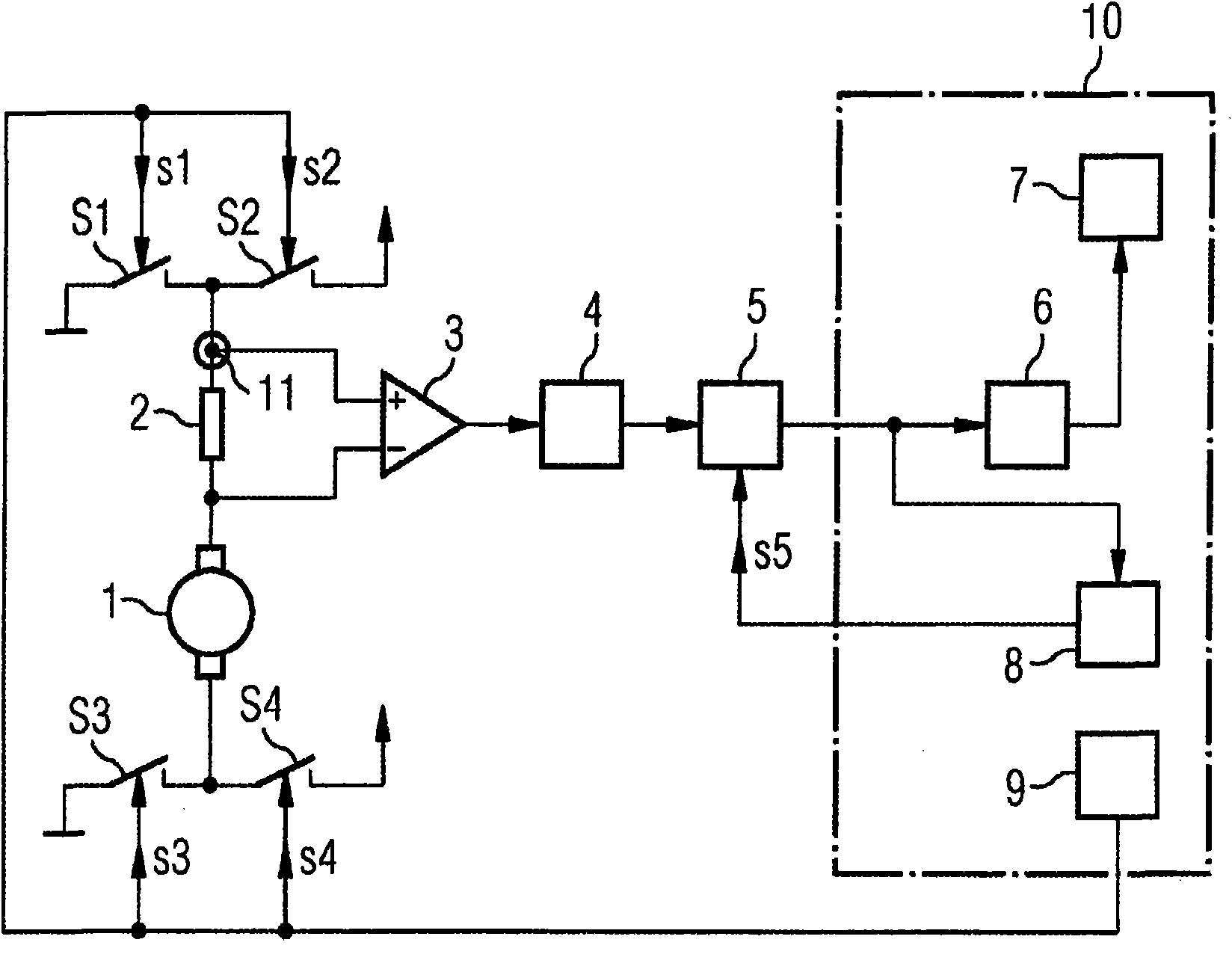
[0017] The window is moved by a DC motor 1 which is switched on and off by a motor controller 9 . Depending on which direction the motor turns, the window is opened or closed.

[0018] To open the window, the motor controller 9 supplies a control signal s4 to the switch S4 and a control signal s1 to the switch S1 . Control signal s4 brings switch S4 to a conductive state. Control signal s1 brings switch S1 to a conductive state. The motor current is thus grounded from a power supply (not shown) via switch S4 , motor 1 , measuring resistor 2 and switch S1 .

[0019] To close the windows, the motor controller 9 supplies a control signal s2 to a switch S2 and a control signal s3 to a switch S3. Control signal s2 brings switch S2 to a conductive state. Control signal s3 brings switch S3 to a conductive state. The current is thus grounded from a power supply (not shown) via switch S2 , measuring resistor 2 , motor 1 and switch S3 .

[0020] figure 1 The upper interface of th...


PUM


Abstract

The invention relates to a method and a device for determining the position of a closing part of a vehicle, that can be moved by a direct-current motor. A motor current signal is derived from the direct-current motor and converted into a digital signal by means of an analog-digital converter. The signal is filtered and forwarded to a position counter for counting the current ripple. The scanning frequency of the analog-digital converter is modified according to the rotational speed of the direct-current motor.

Description

technical field [0001] The invention relates to a method and a device for positioning a movable closure of a motor vehicle. Background technique [0002] Movable closures of automobiles, such as sunroofs and window regulators, are equipped with positioning structures. This positioning mechanism is necessary in order for the window or sunroof to stop in a predetermined position. Such a positioning mechanism is also necessary to ensure pinching protection. [0003] In cost-effective systems, positioning is achieved by counting commutator waves (Kommutator-Stromwelligkeit). The counting of the commutator electrical waves thus takes place, ie the electrical waves referred to below as current ripples are extracted by means of band-pass filtering. For this purpose, the current is typically quickly swept by an analog-to-digital converter, for example with 200 μsec, and then digitally filtered. Since the ripple frequency is determined by the motor speed and the latter can vary s...

Claims


Application Information

Patent Timeline
Patent Type & Authority Applications(China)
IPC IPC(8): H02P7/00B60R16/037G01P3/489
CPCH02P2203/09H02P7/0044H02P7/0094G05D3/127H02P7/04
Inventor R·莫拉韦克
Owner CONTINENTAL AUTOMOTIVE GMBH
Why Eureka
Try Eureka