Waste gas treatment device for biological fermentation tank

A technology of waste gas treatment device and biological fermentation tank, which is applied in the direction of dispersed particle filtration, dispersed particle separation, chemical instruments and methods, etc., and can solve the problems of complex operation and poor treatment effect

Inactive Publication Date: 2021-05-11
广州万为通达科技有限公司
View PDF8 Cites 3 Cited by
  • Summary
  • Abstract
  • Description
  • Claims
  • Application Information

AI Technical Summary

Problems solved by technology

[0004] In order to overcome the shortcomings of poor treatment effect and complicated operation, the technical problem of the present invention is to provide a biolog

Method used


Image

  • Waste gas treatment device for biological fermentation tank
  • Waste gas treatment device for biological fermentation tank
  • Waste gas treatment device for biological fermentation tank

Examples


Embodiment 1

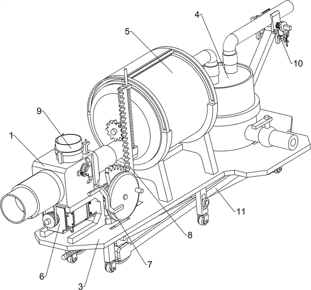
[0094]A biological fermenter exhaust gas treatment device, such asfigure 1 withfigure 2 As shown, there is an air tube 1, a dust plate 2, a bottom plate 3, a disinfection mechanism 4, and a filter mechanism 5, and the upper side of the bottom plate 3 is connected to the air pipe 1, the inner wall of the air pipe 1 is connected to the upper side of the bottom plate 3. The disinfecting mechanism 4 is connected, and the filter mechanism 5 is connected to the upper side of the bottom plate 3.

[0095]When the device needs to be used, the user can pour the disinfection water into the disinfection mechanism 4, pull up the filter mechanism 5 up, put the activated carbon into the filter mechanism 5, pull the filter mechanism 5 down, and put the exhaust gas input disinfection mechanism 4, The exhaust gas is disinfected by the disinfection mechanism 4 to achieve a purpose of disinfection of exhaust gas, and the exhaust gas enters the filter mechanism 5, the exhaust gas is subjected to secondary ...

Embodiment 2

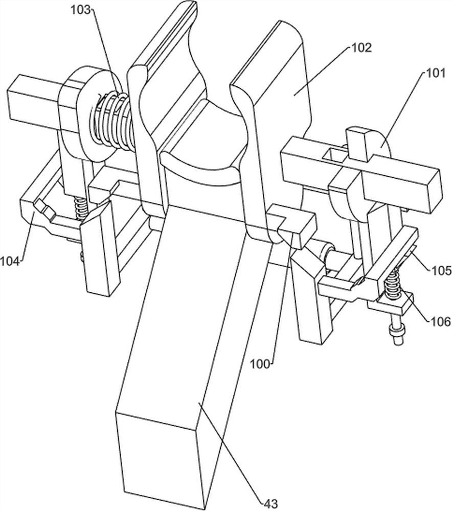
[0097]On the basis of Example 1, such asimage 3 As shown, the disinfection mechanism 4 includes a sterilizing tub 40, an intake pipe 41, a spherical valve 42, and a first support block 43, and the upper side of the bottom plate 3 is connected to the first support block 43, and the inner side of the first support block 43 is connected to the disinfecting bucket 40, On the upper side of the sterilizer 40 is connected to the air pipe 41, the spherical valve 42 is connected to the right side of the sterilizer 40, and the spherical valve 42 passes through the sterilizing bucket 40.

[0098]When the device needs to be used, the user can pour the disinfection water into the disinfection tub 40, pull the filter mechanism 5 up, and place the activated carbon into the filter mechanism 5, pull the filter mechanism 5 downward, and pull the exhaust gas into the trachea 41. The exhaust gas enters the disinfection barrel 40 through the intake pipe 41, and the exhaust gas is disinfected once by disinf...


PUM


Abstract

The invention relates to waste gas treatment, in particular to a waste gas treatment device for a biological fermentation tank. The invention aims to provide the waste gas treatment device for the biological fermentation tank, and the device can effectively adsorb waste gas, accelerate the waste gas treatment rate and simplify the operation process. According to the technical scheme, the biological fermentation tank waste gas treatment device comprises a gas outlet pipe connected to the top side of a bottom plate, a dustproof plate connected with the inner wall of the gas outlet pipe, a disinfection mechanism connected with the top side of the bottom plate, and a filtering mechanism connected with the top side of the bottom plate. Through cooperation of a disinfection barrel, a gas inlet pipe, a spherical valve and a first supporting block, the purpose of performing primary disinfection on waste gas is achieved.

Description

Technical field[0001]The present invention relates to an exhaust gas treatment, and more particularly to a biological fermenter exhaust treatment device.Background technique[0002]Fermentation is a reaction process of microbial growth and chemical changes, decomposing organic matter, producing and accumulating specialized metabolites, microorganisms are fermented products, and the exhaust gas generated by the fermentation production process is a complex organic substance, such as alcohol, aldehyde. , Ketone, ether, and organic acid, etc., characteristics of high temperatures, high humidity, dust containing dust, the fermentation of microorganisms, also produce a large amount of carbon dioxide, acidic gas, and odor, can not be discharged directly into the atmosphere, requiring purification treatment Although the existing exhaust unit is simple, the processing effect is poor, and the emission standard cannot be reached.[0003]The present invention is treated for the exhaust gas produced...

Claims


Application Information

Patent Timeline
IPC IPC(8): B01D53/04B01D53/78B01D53/38B01D46/10
CPCB01D53/04B01D53/78B01D53/38B01D46/10
Inventor 高翠翠
Owner 广州万为通达科技有限公司
Why Eureka
Try Eureka