Finished product shot blasting machine for metal heat treatment

A technology of metal heat treatment and shot blasting machine, which is applied to metal processing equipment, used abrasive treatment devices, abrasive jet machine tools, etc., and can solve problems such as difficult cleaning, parts interference, and product quality impact.

Pending Publication Date: 2021-05-11
厦门澄志精密科技有限公司
View PDF8 Cites 1 Cited by
  • Summary
  • Abstract
  • Description
  • Claims
  • Application Information

AI Technical Summary

Problems solved by technology

[0004] However, in the daily work process, it can be found that some workpieces will fall out with other workpieces that have been shot blasted after the end of shot blasting, which will affect the quality of the product, and, in the process o

Method used


Image

  • Finished product shot blasting machine for metal heat treatment
  • Finished product shot blasting machine for metal heat treatment
  • Finished product shot blasting machine for metal heat treatment

Examples


Embodiment Construction

[0022] The following will clearly and completely describe the technical solutions in the embodiments of the present invention with reference to the accompanying drawings in the embodiments of the present invention. Obviously, the described embodiments are only some, not all, embodiments of the present invention.

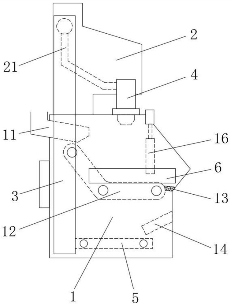
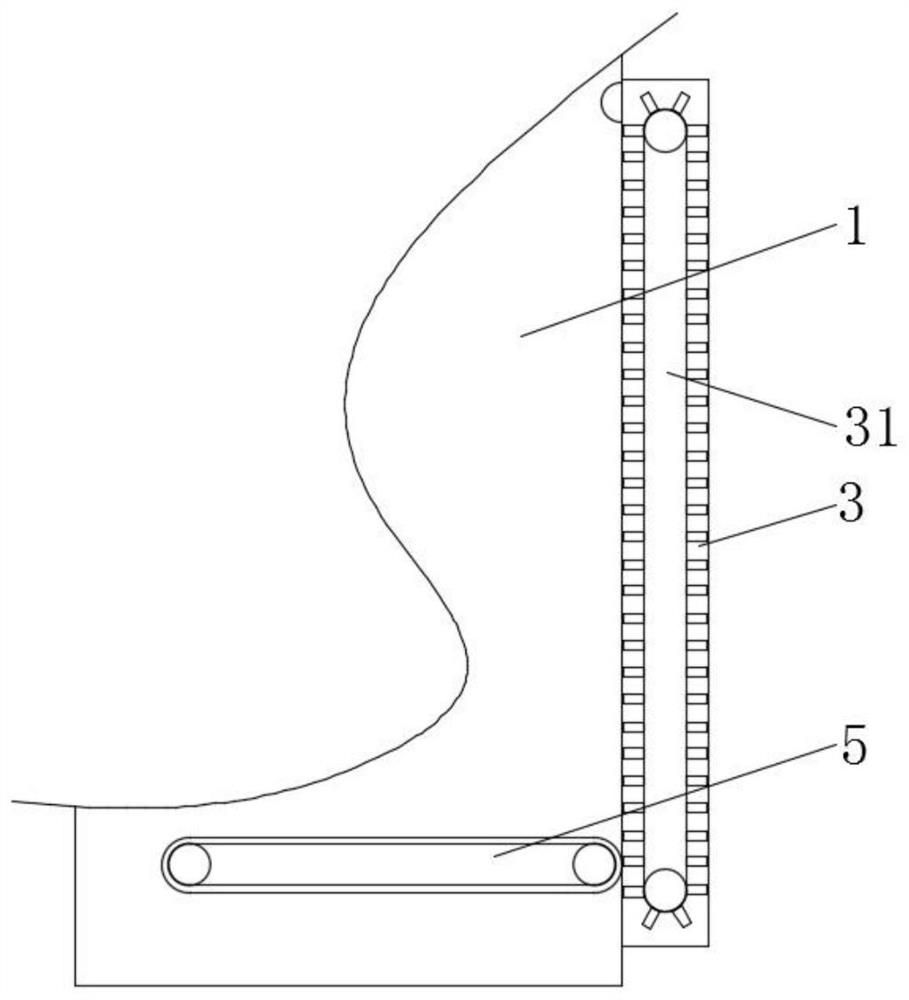
[0023] refer to Figure 1-4 , a finished shot blasting machine for metal heat treatment, comprising a lower base 1, an upper top base 2 and a shot blaster 4, the lower base 1 and the upper fixed base 2 are integrally arranged (a controller is installed on the side wall of the lower base 1 ), and a side seat 3 is also welded on its side wall, and a hoist 31 is installed in the side seat 3, which is used to re-elevate the projectile into the shot blaster 4, and the lower base 1 is provided with a feed pipe 11. The outlet of the pipe 11 is located above the top of the conveying crawler 12, and both sides of the interior are welded with partitions 15, and a conveying cra...


PUM


Abstract

The invention relates to the technical field of shot blasting machines, in particular to a finished product shot blasting machine for metal heat treatment. The finished product shot blasting machine comprises a lower bottom seat, an upper top seat and an impeller head. The lower bottom seat and the upper top seat are integrally arranged, a side seat is welded to the side walls of the lower bottom seat and the upper top seat, and an elevator is mounted in the side seat. A feeding pipe is arranged on the lower bottom seat, partition plates are welded to the two sides of the interior of the lower bottom seat, and a conveying crawler belt is arranged between the partition plates on the two sides. A sliding plate is welded to the inner wall of one side of the lower bottom seat, sieve holes are formed in the sliding plate, and one end of the sliding plate is connected with the tail end of the conveying crawler belt end to end. A conveying belt is installed at the position, close to the bottom, in the lower bottom seat and is located below the sliding plate, and a baffle is movably arranged above the tail end of the conveying crawler belt through an electric push rod. The impeller head is installed between the lower bottom seat and the upper top seat and located above the conveying crawler belt, and a shot channel is connected between the side seat and the impeller head. According to the finished product shot blasting machine, the shot blasting effect can be improved, so that workpieces can be treated more thoroughly; and dust and debris in the machine can be conveniently removed.

Description

technical field [0001] The invention relates to the technical field of shot blasting machines, in particular to a finished shot blasting machine for metal heat treatment. Background technique [0002] With the rapid development of industry, the steel industry has also developed rapidly. In the field of steel structure processing and production, a shot blasting machine is needed, which uses the high-speed projectiles thrown by the shot blaster to clean or strengthen the casting equipment on the surface of the casting. Shot blasting machines have drum type, crawler type and other types of different structures. [0003] When the crawler shot blasting machine is working, put the workpiece into the rubber crawler roller, the operator presses the "run" button, the door of the shot blasting chamber is closed pneumatically, the shot blasting starts, the crawler moves forward, and the workpiece rolls continuously. The high-efficiency and powerful shot blasting device shoots the shot...

Claims


Application Information

Patent Timeline
IPC IPC(8): B24C1/08B24C3/00B24C5/00B24C9/00
CPCB24C1/086B24C3/00B24C5/00B24C9/006
Inventor 陈昊
Owner 厦门澄志精密科技有限公司
Why Eureka
Try Eureka