Lifting hook device of shot blasting machine

A technology of shot blasting machine and hook, which is applied in the direction of transportation and packaging, load hanging components, etc., can solve the problems of product damage, shot blasting dead angle, etc., and achieve the effects of saving time, improving yield, and simple structure

Inactive Publication Date: 2016-04-20
JIANGSU ZHENGCHI ELECTROMECHANICAL
View PDF5 Cites 3 Cited by
  • Summary
  • Abstract
  • Description
  • Claims
  • Application Information

AI Technical Summary

Problems solved by technology

In the end, it can only be thrown to 2 surfaces. The other surfaces rely on the steel balls to bounce around in the shot blasting machine and bounce back to the surface of the product for shot blasting. is the product damaged

Method used


Image

  • Lifting hook device of shot blasting machine
  • Lifting hook device of shot blasting machine
  • Lifting hook device of shot blasting machine

Examples


Embodiment Construction

[0026] In order to further illustrate the technical means adopted by the present invention and the technical effects achieved, the following will be described in detail in conjunction with the accompanying drawings and specific embodiments.

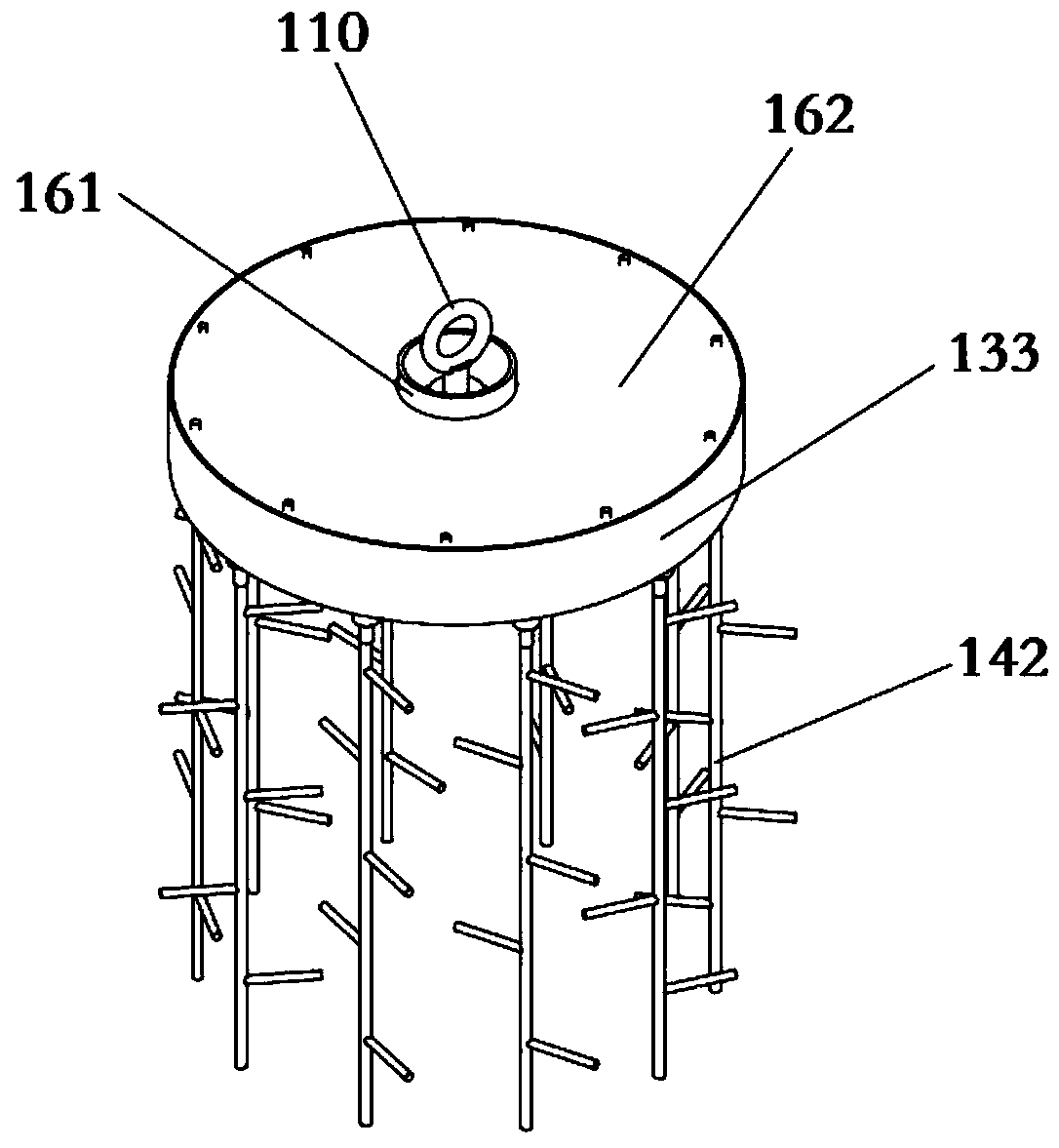
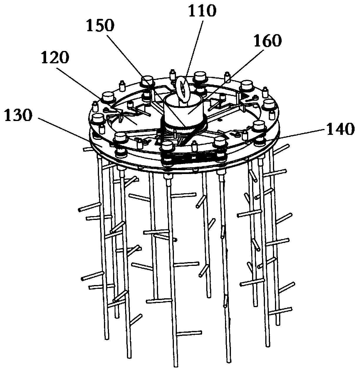
[0027] refer to figure 1 and figure 2 , The hook device of the shot blasting machine of the present invention includes a hook 110 , a supporting chassis 120 , an annular bracket 130 , a hanger 140 , a fixed sprocket 150 and a sealing structure 160 . The top of the hook 110 is provided with an O-shaped hanging ring, and the bottom is fixedly connected with the support chassis 120, and the support chassis 120 is generally circular.

[0028] The fixed sprocket 150 is sheathed in the middle of the hook 110 and is stationary relative to the hook 110 .

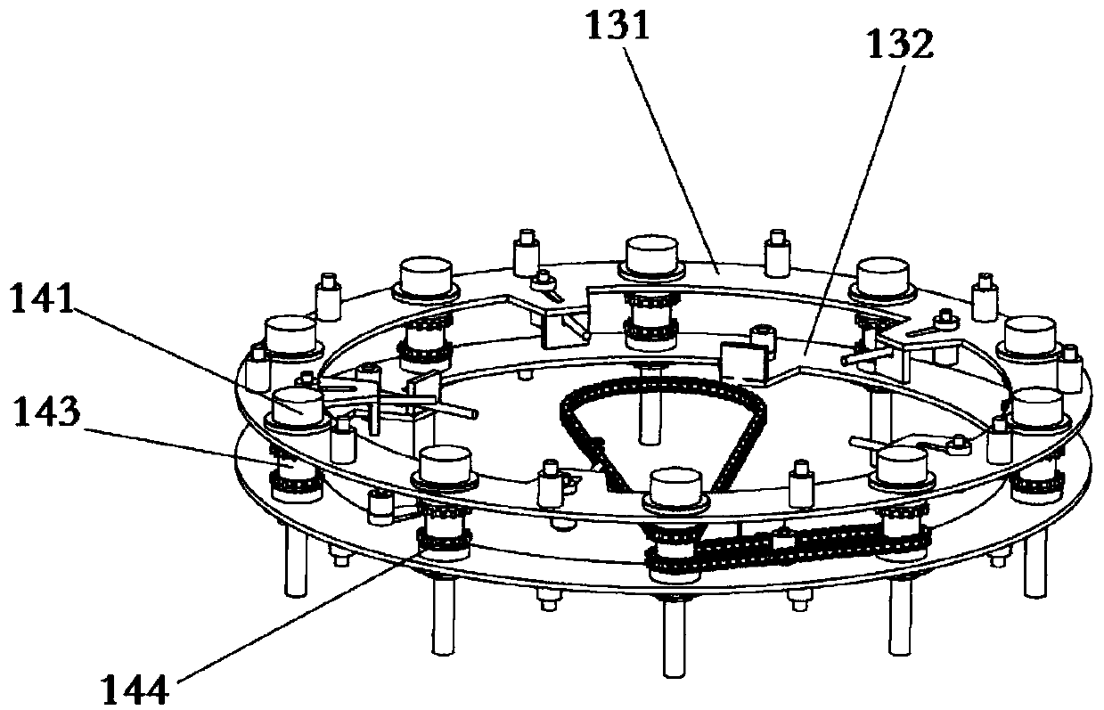
[0029] refer to image 3 , the ring bracket 130 includes two upper brackets 131 and lower brackets 132 of the same shape, the upper bracket 131 and the lower bracket 132 are both in the sha...


PUM


Abstract

The invention provides a lifting hook device of a shot blasting machine. The lifting hook device adopts the structure that a fixed chain wheel is fixed, a lifting hook drives a supporting base plate and an annular bracket to rotate, and lifting frames rotating along with the annular bracket are driven by a chain on the fixed chain wheel to further rotate; besides, an inner ring baffle, an inner ring supporting plate, an annular sealing baffle, a lower bracket, the supporting base plate and the fixed chain wheel are combined to form a sealing space, so that dust and sundries cannot enter the sealing space. The lifting hook device disclosed by the invention has the advantages that the structure is simple, the design is ingenious, multiple rotation is realized, dead angle remains do not exist, time is saved, and the working efficiency is improved.

Description

technical field [0001] The invention relates to a shot blasting device, in particular to a hook device of a shot blasting machine. Background technique [0002] The hook used in the traditional shot blasting machine is an integral rotating bifurcated type, just like the trunk and branches. The products that need to be shot are hung on the branches respectively, and then the trunk rotates along the axis. The product revolves around the axis of the trunk on one side, and the product itself does not Does not rotate. When the steel shot is thrown to the product, it can only be thrown to the outward side of the product, and the back of the product facing the steel shot becomes a dead angle, which cannot be completely cleaned. It is necessary to turn the product over and perform secondary shot blasting. The time for one shot blasting is 10 minutes. After the first shot blasting, it takes 10 minutes to turn over and the second shot blasting time is 10 minutes, resulting in a total...

Claims


Application Information

Patent Timeline
Patent Type & Authority Applications(China)
IPC IPC(8): B66C1/10
CPCB66C1/10
Inventor 印常华
Owner JIANGSU ZHENGCHI ELECTROMECHANICAL
Why Eureka
Try Eureka