Stroke drive mechanism for composite material forming equipment

A technology for forming equipment and composite materials, which is applied in the field of stroke drive mechanism for composite material forming equipment, and can solve problems such as uneven mixing of resin solution and modifier, easy formation of dead angles, etc.

Active Publication Date: 2021-05-11
NANJING XIAOZHUANG UNIV
View PDF4 Cites 0 Cited by
  • Summary
  • Abstract
  • Description
  • Claims
  • Application Information

AI Technical Summary

Problems solved by technology

[0003] Because the resin solution is very viscous, the stroke drive mechanism of the existing composite material molding equipment cannot drive the mixing rod to fully mix the resin solution after adding the modifier, and it is easy to form a dead angle, so that the resin solution and the modifier are not mixed well. uniform

Method used


Image

  • Stroke drive mechanism for composite material forming equipment
  • Stroke drive mechanism for composite material forming equipment
  • Stroke drive mechanism for composite material forming equipment

Examples


Embodiment Construction

[0029] The technical solutions in the embodiments of the present invention will be clearly and completely described below in conjunction with the embodiments of the present invention. Apparently, the described embodiments are only some of the embodiments of the present invention, not all of them. Based on the embodiments of the present invention, all other embodiments obtained by persons of ordinary skill in the art without creative efforts fall within the protection scope of the present invention.

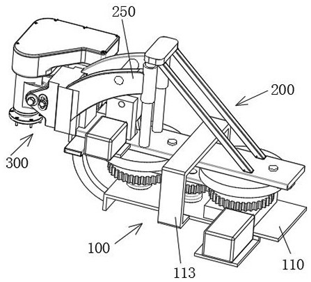
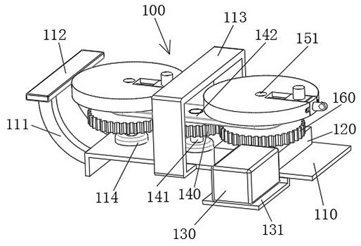
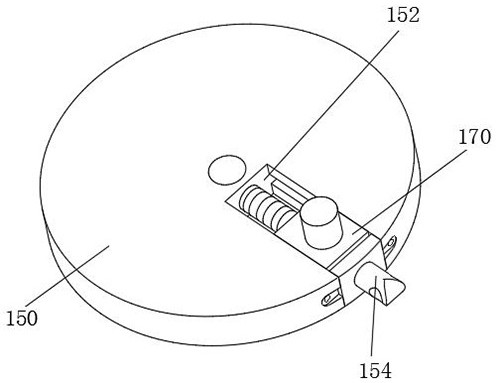
[0030] see Figure 1-8As shown, a stroke driving mechanism for composite material molding equipment includes a revolution module 100, and the revolution module 100 includes a bottom plate 110, and gears 2 160 are arranged above both ends of the top surface of the bottom plate 110, and the inner wall of the gear 2 160 is fixed. Shaft 2 151 is connected, and gear 1 140 is arranged between two gears 160. The inner wall of gear 1 140 is fixedly connected with shaft 1 141, and the bott...


PUM


Abstract

The invention relates to the technical field of stroke drive mechanisms, in particular to a stroke drive mechanism for composite material forming equipment. The stroke drive mechanism comprises a revolution module, wherein the revolution module comprises a bottom plate I, gears II are arranged above the two ends of the top surface of the bottom plate I, and the inner walls of the gears II are fixedly connected to shaft rods II; a gear I is arranged between the two gears II, the inner wall of the gear I is fixedly connected to a shaft rod I, and the bottom end of the shaft rod I and the bottom end of one shaft rod II are rotationally connected to a rotating seat. According to the invention, through the arrangement of the revolution module and a lifting module, the output shaft can revolve under the driving of the revolution module while rotating, and can lift up and down under the driving of the lifting module, so that the output shaft can drive a stirring rod to fully mix and stir raw materials; through the arrangement of a slide block, the revolution radius of the output shaft in an output arm is changed to better adapt to a stirring container, the periphery of the inner wall of the stirring container is mixed, and dead angles are avoided.

Description

technical field [0001] The invention relates to the technical field of stroke drive mechanisms, in particular to a stroke drive mechanism for composite material molding equipment. Background technique [0002] The commonly used resins for fiber-reinforced resin-based composites are epoxy resins and unsaturated polyester resins, and various modifiers are added and mixed as needed during the proportioning process of the resins. [0003] Because the resin solution is very viscous, the stroke drive mechanism of the existing composite material molding equipment cannot drive the mixing rod to fully mix the resin solution after adding the modifier, and it is easy to form a dead angle, so that the resin solution and the modifier are not mixed well. uniform. Contents of the invention [0004] In order to overcome the above-mentioned technical problems, the object of the present invention is to provide a stroke drive mechanism for composite material molding equipment, through the s...

Claims


Application Information

Patent Timeline
Patent Type & Authority Applications(China)
IPC IPC(8): B29B7/06B29B7/16B29B7/22
CPCB29B7/06B29B7/16B29B7/22
Inventor 万轶王永王莹滢陈影
Owner NANJING XIAOZHUANG UNIV
Why Eureka
Try Eureka