Bicycle dragging device

A towing device and bicycle technology, which are applied to bicycles, foldable bicycles, motor vehicles, etc., can solve the problems of inconvenient disassembly and assembly, insufficient position of connecting rods, increased turning radius, etc., and achieve convenient assembly and disassembly and convenient use. Fast, reduced turning radius effect

Inactive Publication Date: 2021-05-11
陈宇轩
View PDF0 Cites 1 Cited by
  • Summary
  • Abstract
  • Description
  • Claims
  • Application Information

AI Technical Summary

Problems solved by technology

[0003] 1) When the cart turns, the turning point of the trolley is also at the front of the cart, so the entire turning radius of the trolley is approximately equal to the original turning radius of the cart plus the length of the connecting rod and the length of the trolley, and the turning radius increases. This leads to an increase in danger when turning during riding (a larger turning area is required, for example, after the big car turns over, the small car needs to borrow the side lane to realize the turning, increasing the risk of the small car)
[0004] 2) The connecting rod must be connected to the connecting rod under the seat of the large car. For some cars, the position of the connecting rod under the seat is not enough, or when an adult does not need such a high seat, it cannot provide enough connecting space. In this case, it is not possible to use
[0005] 3) After arriving at the destination, after the trolley is separated from the cart, the connecting rod of the cart cannot be retracted, causing a connecting rod to be dragged behind the cart, which increases the danger behind the cart
Need to use special tools to separate, it is not convenient to disassemble
[0007] 5) After using the above connecting rod, the rear seat of the cart can no longer carry goods or people, which limits the normal use of the cart

Method used


Image

  • Bicycle dragging device
  • Bicycle dragging device
  • Bicycle dragging device

Examples


Embodiment Construction

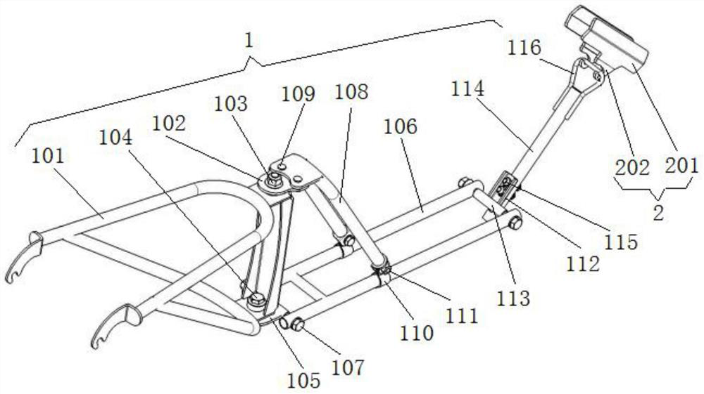
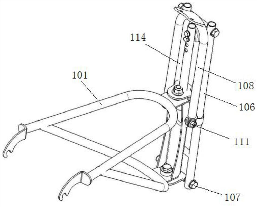
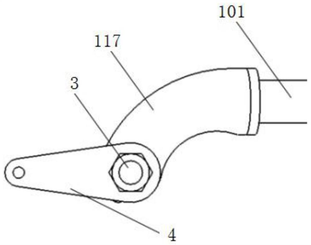
[0037] like Figure 1-7 As shown, a bicycle dragging device includes a folding connecting frame 1 and a trolley connecting frame 2, and the front end of the folding connecting frame 1 is clamped on the rear connecting shaft 3 of the cart and locked and positioned by a fastening assembly. The rear end of the folding connecting frame 1 is connected with the hook 202 at the front end of the said trolley connecting frame 2, and the rear end of said trolley connecting frame 2 is clamped and connected on the trolley frame 7, and the front wheel of the trolley is lapped on the said trolley frame 7 during connection. The folding connecting frame 1 is fixed and not in contact with the ground, and the folding connecting frame 1 is provided with a rotating shaft, and the rotating shaft is located between the rear wheel of the cart and the front wheel of the trolley; when the folding connecting frame 1 is in operation Fully open, folded away when not working.

[0038] Specifically, such ...


PUM


Abstract

The invention discloses a bicycle dragging device which comprises a folding connecting frame and a trolley connecting frame; the front end of the folding connecting frame is connected to a large vehicle rear connecting shaft in a clamped mode and locked and positioned through a fastening assembly, and the rear end of the folding connecting frame is connected with a hook at the front end of the trolley connecting frame; the rear end of the trolley connecting frame is connected to the trolley frame in a clamped mode; during connection, a trolley front wheel is in lap joint with the folding connecting frame, is positioned immovably and does not make contact with the ground; a rotating shaft is arranged on the folding connecting frame, and the rotating shaft is located between the cart rear wheel and the trolley front wheel; the folding connecting frame is completely opened when working and is folded when not working. The bicycle dragging device is ingenious in conception, compact and reasonable in structure, convenient and fast to mount and dismount, is in an unfolded state when in use, is folded and placed behind a rear seat of a cart when not in use, does not affect the man-carrying and object-carrying functions, reduces the overall rotating radius, is convenient and fast to fold and store, and does not affect the riding safety.

Description

technical field [0001] The invention relates to the field of bicycle moving auxiliary equipment, in particular to a bicycle dragging device. Background technique [0002] At this stage, when adults need to take minors to ride outdoors, they usually need to connect two independent bicycles to ensure the safety of minors riding on roads and other dangerous places. . The general connection method in the market at this stage uses a connecting rod with an arc structure to fix the seat part support rod of the big car for adults and the front part of the small car for minors to realize the function of connecting and dragging. This connection method has the following problems: [0003] 1) When the cart turns, the turning point of the trolley is also at the front of the cart, so the entire turning radius of the trolley is approximately equal to the original turning radius of the cart plus the length of the connecting rod and the length of the trolley, and the turning radius increas...

Claims


Application Information

Patent Timeline
Patent Type & Authority Applications(China)
IPC IPC(8): B62K15/00
CPCB62K15/006B62K27/12B62K27/003
Inventor 陈宇轩陈家欣徐运帷
Owner 陈宇轩
Why Eureka
Try Eureka