Electronic connector detection and discharging device and method

A technology of electronic connectors and detection mechanisms, applied in the directions of transportation and packaging, conveyor objects, sorting, etc., can solve the problem of increasing the cost of equipment cylinders, reducing friction, reducing the accuracy of rubber core positioning fixtures to receive rubber cores, etc. question

Active Publication Date: 2021-05-11
DONGGUAN YUSEN PRECISION TERMINAL
View PDF7 Cites 0 Cited by
  • Summary
  • Abstract
  • Description
  • Claims
  • Application Information

AI Technical Summary

Problems solved by technology

[0004] The prior art has the following deficiencies: 1. When feeding the rubber core, the rubber core positioning jig is first transported to the receiving slide in the jig receiving assembly; The movement of the tool will receive and position the rubber core conveyed by the rubber core conveyor belt, and the action of the jig push-out component will directly push the rubber core positioning jig along the receiving slideway to complete the rubber core feeding process; and in this way, the receiving slideway relies on its The friction between itself and the rubber core positioning jig drives the rubber core positioning jig to move; when the jig push-out component pushes the rubber core positioning jig directly along the receiving slide for many times, the outer surface of the rubber core positioning jig Due to the relative movement between the inner surface of the receiving slideway and the inner surface of the receiving slideway, there will be a certain degree of wear and tear, which will make the contact surface between the two smoother; thus reducing the friction between the rubber core positioning fixture and the receiving slideway, and the friction between the two It is not enough to make the receiving slideway drive the rubber core positioning jig to move; then the rubber core positioning jig cannot move to the set position, reducing the accuracy of the rubber core positioning jig to receive the rubber core
3. When conveying the rubber core positioning jig, first use the positioning head to drive the cylinder to drive the jig positioning head to match the side groove of the rubber core jig, and then the jig drives the cylinder to drive the positioning head to drive the cylinder to move and then drive the rubber core to locate The jig moves along the jig conveying slideway to the next station to complete the jig conveying process; in this way, the movement of the jig positioning head is driven by the positioning head drive cylinder, that is, the number of jig positioning heads and the positioning head The number of driving cylinders is corresponding; when the jig conveying slideway is long and needs to transport multiple rubber core positioning jigs at the same time, more jig positioning heads and more positioning head driving cylinders are required; thus causing the cylinder in the equipment to The quantity is large, which increases the cylinder cost of the equipment
4. When performing flip detection on the electronic connector, the electronic connector is first manually moved to the detection station and the electronic connector is turned over for detection, and then the electronic connector is moved to the jig conveying slide to output and unload to complete the electronic Connector detection process; in this method, the back and forth moving and flipping of electronic connectors are all done manually, which increases the labor intensity and reduces the detection efficiency

Method used


Image

  • Electronic connector detection and discharging device and method
  • Electronic connector detection and discharging device and method
  • Electronic connector detection and discharging device and method

Examples


Embodiment 1

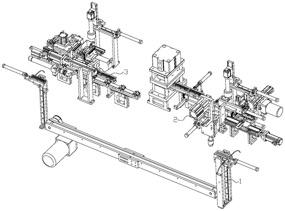
[0038] Such as figure 1 An electronic connector assembly equipment is shown, which includes a workbench and a jig circulation device 1 fixed on the workbench, a feeding riveting device 2 and a detection and unloading device 3; both ends of the jig circulation device 1 are respectively connected to The input end of the feeding riveting device 2 is connected with the output end of the detection and blanking device 3; the output end of the feeding riveting device 2 is connected with the input end of the detection and blanking device 3; the jig circulation device 1 is used for the circulation of the rubber core positioning jig Conveying; the feeding and riveting device 2 is used for feeding the rubber core and pins and the riveting between the two; the detecting and unloading device 3 is used for detecting and unloading the assembled electronic connector.

[0039] The product flow direction of the electronic connector is: jig circulation device 1 to feeding riveting device 2 to de...


PUM


Abstract

The invention relates to the field of electronic connectors, in particular to an electronic connector detection and discharging device and method and electronic connector assembling equipment. The device comprises a jig conveying mechanism, an overturning detection mechanism and a screening and discharging mechanism. The jig conveying mechanism, the overturning detection mechanism and the screening and discharging mechanism are all fixed to a workbench. The jig conveying mechanism is in sliding fit with a rubber core positioning jig, and an overturning detection station and a discharging station in the jig conveying mechanism are connected with the input end of the overturning detection mechanism and the input end of the screening and discharging mechanism correspondingly. By arranging the jig conveying mechanism, the number of air cylinders in the device is reduced, and the air cylinder cost of the device is reduced; by arranging the overturning detection mechanism, the labor intensity of workers is reduced, and the detection efficiency of electronic connectors is improved; and by arranging the screening and discharging mechanism, rapid discharging of the electronic connectors is guaranteed, and the automation degree of the device is improved.

Description

technical field [0001] The invention relates to the field of electronic connectors, in particular to an electronic connector detection and blanking device and method, and electronic connector assembly equipment. Background technique [0002] An electronic connector is a conductor device that bridges two conductors on a circuit so that current or signals can flow from one conductor to another. It is widely used in various electrical circuits and plays the role of connecting or disconnecting current or signals. An electronic connector is an electrical system that can provide a separable interface to connect two sub-electronic systems. Simply put, the components used to complete electrical connections between circuits or electronic machines become connectors, that is, both bridge between. Electronic connectors can be used as electrical or electronic transmission connection parts between circuits, components and systems, so that power, signals, or current can flow stably and r...

Claims


Application Information

Patent Timeline
Patent Type & Authority Applications(China)
IPC IPC(8): B65G47/82B65G47/248B65G47/74B07C5/38
CPCB65G47/82B65G47/248B65G47/74B07C5/38
Inventor 何振华胡全远谭胜褚小鹏
Owner DONGGUAN YUSEN PRECISION TERMINAL
Why Eureka
Try Eureka