Coiling frame for earcap rope

A technology of earmuffs and winding wires, which is applied in the field of earmuff rope production, can solve the problems of easy formation of high piles and the inability to fill the inner cavity of the packing box, so as to achieve the effect of improving elasticity

Pending Publication Date: 2021-05-11
绿沅(上海)实业有限公司
View PDF5 Cites 0 Cited by
  • Summary
  • Abstract
  • Description
  • Claims
  • Application Information

AI Technical Summary

Problems solved by technology

[0003] In view of the above-mentioned related technologies, the inventor believes that the existing direct dependence on the gravity of the rope makes the rope fall into the packaging box, and the rope is easy to form a high pile in the box, which cannot fill the inner cavity of the packaging box.

Method used


Image

  • Coiling frame for earcap rope
  • Coiling frame for earcap rope
  • Coiling frame for earcap rope

Examples


Embodiment 1

[0031] Embodiment 1, the first aspect The embodiment of the present application discloses a coiling frame for ear loop cords.

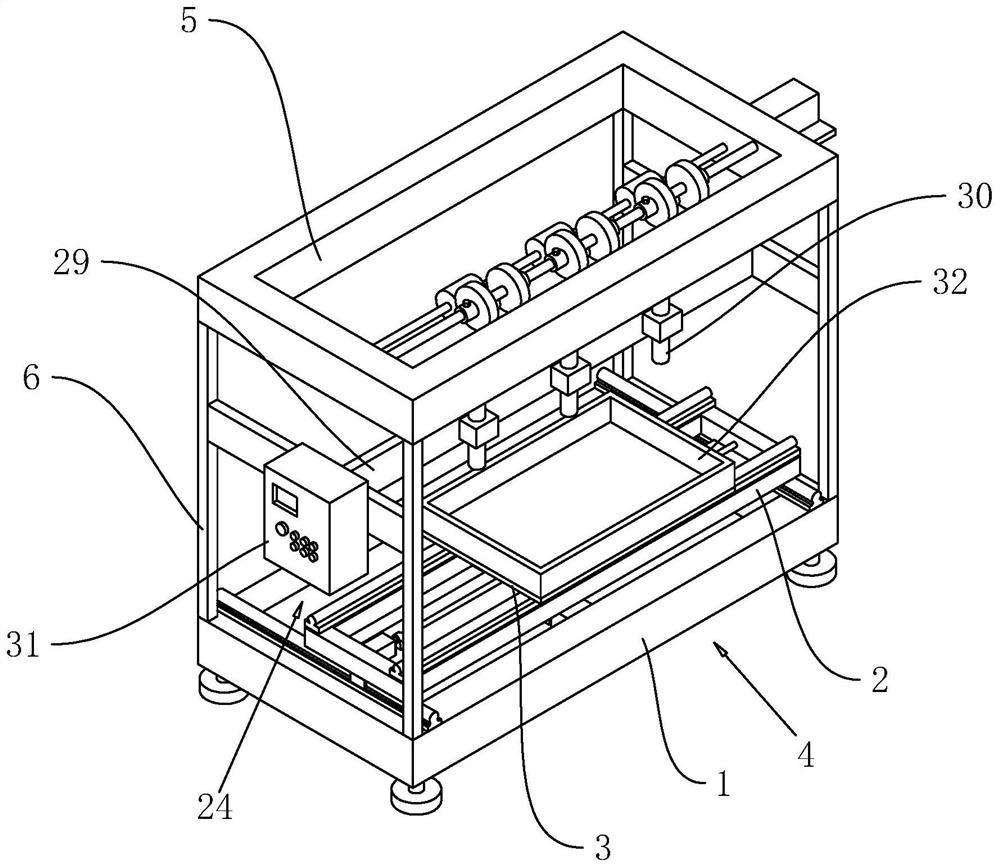
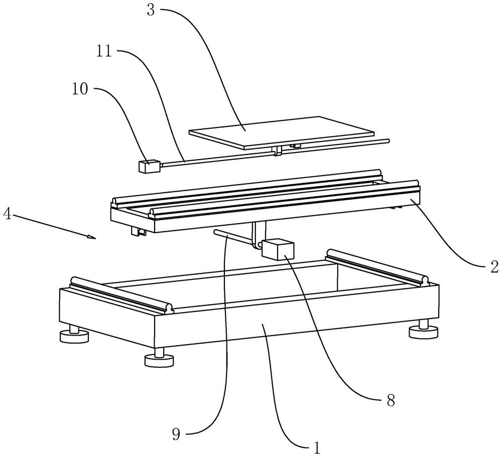
[0032] refer to figure 1 , a coil frame for ear loop ropes, comprising a bottom frame 1, the bottom frame 1 is a rectangular frame, the bottom frame 1 is placed on the ground through feet, an installation frame 2 is arranged on the upper surface of the bottom frame 1, the installation frame 2 Slide along the width direction of the bottom frame 1, the upper surface of the installation frame 2 is provided with a placement plate 3, the placement plate 3 slides along the length direction of the bottom frame 1, the sliding direction of the placement plate 3 is the same as that of the installation frame 2 The sliding direction is set vertically, so that the packing carton used to accommodate the ear loop rope is placed on the upper surface of the placing board 3, and both the placing board 3 and the packing carton can slide along the length direction of the...

Embodiment 2

[0040] Embodiment 2, the second aspect The embodiment of the present application discloses a winding frame for earloop cords.

[0041] refer to Figure 4 The difference between the second embodiment and the first embodiment is that the drive assembly 4 includes a third servo motor 12, a third reciprocating lead screw 13 and is arranged on the bottom frame 1 for driving the placement plate 3 along the installation frame 2. The connecting assembly 14 reciprocatingly slides in the length direction, the third servo motor 12 is fixed on the bottom surface of the bottom frame 1, the third reciprocating screw 13 is rotatably connected to the bottom surface of the bottom frame 1, and the third reciprocating screw 13 is coaxially fixed on the bottom surface of the bottom frame 1. On the rotating shaft of the third servo motor 12 , the mounting frame 2 is screwed to the third reciprocating lead screw 13 .

[0042] refer to Figure 4 , the connection assembly 14 includes a rack 15, a g...


PUM


Abstract

The invention relates to the technical field of earcap rope production, in particular to an coiling frame for an earcap rope. The coiling frame comprises a bottom frame, a mounting frame sliding in the width direction of the bottom frame is arranged on the upper surface of the bottom frame, a containing plate sliding in the length direction of the bottom frame is arranged on the upper surface of the mounting frame, a driving assembly used for driving the mounting frame and the placing plate to slide synchronously is arranged on the bottom frame, a top frame is arranged above the mounting frame, vertical rods are fixed to the bottom surfaces of the two ends of the top frame, the vertical rods are fixedly connected with the bottom frame, the placing plate is located below the top frame, and the top frame is provided with a clamping assembly used for the earcap rope to vertically slide downwards. The coiling frame has the effect that the phenomenon of stacking and knotting is difficult to occur in the storage process of the earcap rope.

Description

technical field [0001] The present application relates to the technical field of production of ear loop cords, in particular to a winding frame for ear loop cords. Background technique [0002] It is known that both earmuffs and masks need earloop ropes, which are formed by weaving during the production process. The existing earloop ropes are usually woven with materials such as polyester, nylon, spandex, and core-spun yarn. It is known that the ear loop rope is packed directly after weaving. Before weaving, several yarns are woven into a whole rope through the crochet head, and then the knitted rope is directly dropped into the packing carton, so as to realize the collection of the ear loop rope material. [0003] In view of the above-mentioned related technologies, the inventor believes that the existing direct dependence on the gravity of the rope makes the rope fall into the packing box, and the rope is easy to form a high pile in the box, which cannot fill the inner ca...

Claims


Application Information

Patent Timeline
IPC IPC(8): B65H54/78B65H51/08B65H71/00
CPCB65H54/78B65H51/08B65H71/00B65H2701/35
Inventor 徐煜
Owner 绿沅(上海)实业有限公司
Why Eureka
Try Eureka