Fabricated rest room for construction site
A construction site and assembled technology, which is applied to the parts, applications, and pumping devices of pumping devices for elastic fluids, can solve the problems of poor temperature adjustment effects of air conditioners, and achieve disrupted flow directions and no great difference in indoor and outdoor temperature differences , maintain a stable effect
- Summary
- Abstract
- Description
- Claims
- Application Information
AI Technical Summary
Problems solved by technology
Method used
Image

Examples
Embodiment 1
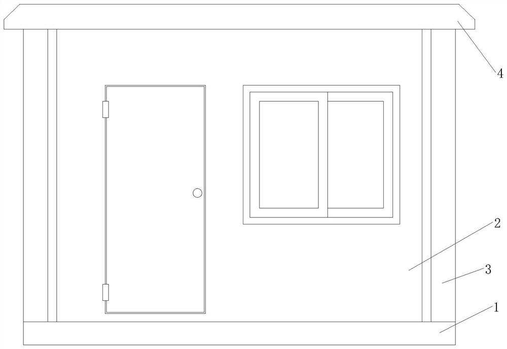
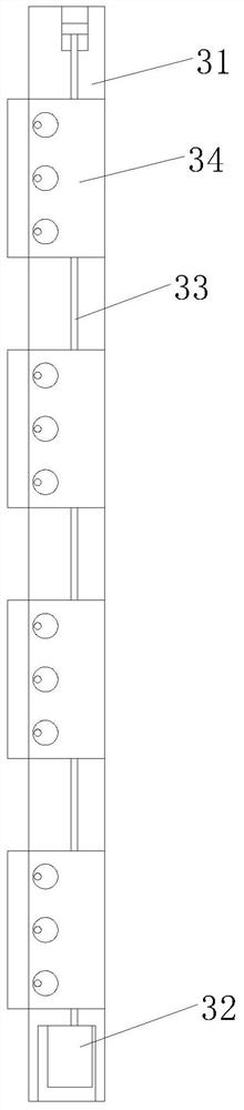
[0027] Such as figure 1 As shown, the present invention provides a prefabricated rest house for a construction site, including a bottom plate 1, four side walls 2 arranged in a cube are arranged above the bottom plate 1, and the side walls 2 are connected by connectors 3. A roof 4 is fixedly installed above the side wall 2, and the connector 3 includes a frame rod 31. A motor 32 is fixedly installed at the inner bottom of the frame rod 31, and a transmission shaft 33 is connected to the output shaft of the motor 32. A ventilator 34 is connected, and the upper end of the transmission shaft 33 is rotatably connected with the upper end inside of the frame rod 31 .
[0028] In this embodiment, the side walls are installed together through the designed frame bar 31, and the ventilator 34 on it operates under the drive of the motor 32 through the transmission shaft 33, cooling and ventilating the internal space of the present invention, which The energy consumption is less, and the...
Embodiment 2
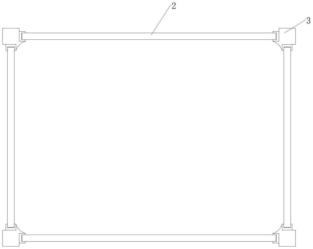
[0030] Such as figure 2 As shown, on the basis of Embodiment 1, the present invention provides a technical solution: the ventilator 34 includes a block 341, the side of the seat block 341 is provided with a fitting opening 342, and the fitting opening 342 is fitted with the side wall 2 Fixedly connected, a sealing plate 343 is rotatably connected to the side of the seat block 341 , the transmission shaft 33 is set through the seat block 341 , and the fan blade group 344 is fixedly installed on the transmission shaft 33 inside the seat block 341 .
[0031] In this embodiment, the air in the room is centrifugally extracted through the designed fan blade set 344 driven by the motor 32 through the transmission shaft 33, and the input of the outside air is completed through the block 341, thereby completing Displacement of air in a room.
Embodiment 3
[0033] Such as image 3 As shown, on the basis of Embodiment 2, the present invention provides a technical solution: the blade set 344 includes a carrier ring a1, and the outer surface of the carrier ring a1 is provided with six diverter plates a2 in an array, and the diverter plates a2 A comb a3 is arranged on the outer surface, and the two ends of the diverter plate a2 are connected by a rear side frame rod a4, and one end of the comb a3 is fixed on the side of the diverter plate a2, and the comb a3 is arc-shaped, Its end is towards the rear side frame bar a4.
[0034] In this embodiment, when the blade set 344 is driven to rotate by the transmission shaft 33, the slope design of the diverter plate a2 can scoop up the air flow, and the air is squeezed to form a high pressure at the intersection of the diverter plate a2 and the carrier ring a1, and The back side of the diversion plate a2 generates a negative pressure due to air flow blocking, so that the air flow outside is ...
PUM
 Abstract
Description
Claims
Application Information
 - R&D
- Intellectual Property
- Life Sciences
- Materials
- Tech Scout
- Unparalleled Data Quality
- Higher Quality Content
- 60% Fewer Hallucinations
Browse by: Latest US Patents, China's latest patents, Technical Efficacy Thesaurus, Application Domain, Technology Topic, Popular Technical Reports.
© 2025 PatSnap. All rights reserved.Legal|Privacy policy|Modern Slavery Act Transparency Statement|Sitemap|About US| Contact US: help@patsnap.com