Novel electronic component thermal resistance test fixture

A technology of electronic components and test fixtures, which is applied to workpiece clamping devices, parts of electrical measuring instruments, measuring devices, etc., and can solve problems such as pin welding contact, short circuit of electronic components, and inability to test

Inactive Publication Date: 2021-05-11
58TH RES INST OF CETC
View PDF6 Cites 2 Cited by
  • Summary
  • Abstract
  • Description
  • Claims
  • Application Information

AI Technical Summary

Problems solved by technology

When conducting thermal resistance tests of electronic components, since the distance between adjacent pins of electronic components is very small, it is usually necessary to solder leads to the pins. Welding will easily lead to soldering contact between adjacent pins, resulting in short circuit of electronic components. test cannot be performed

Method used


Image

  • Novel electronic component thermal resistance test fixture
  • Novel electronic component thermal resistance test fixture

Examples


Embodiment 1

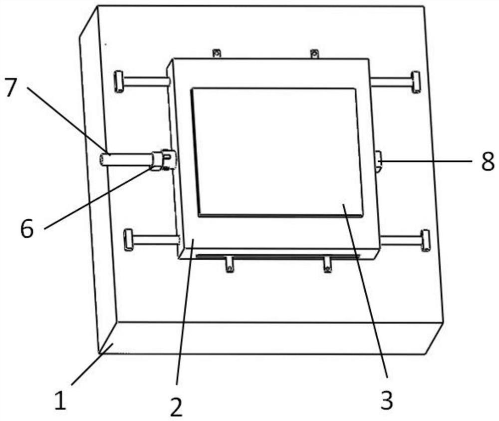
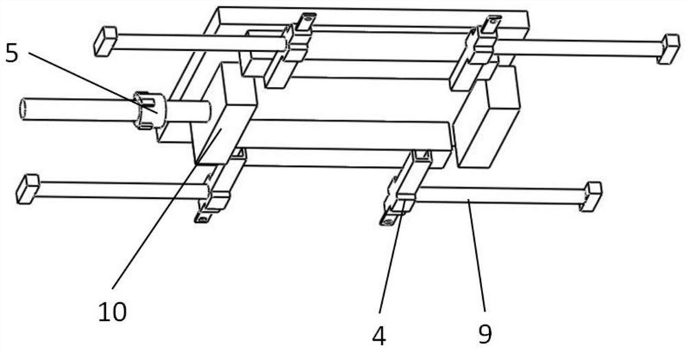
[0022] The invention provides a new type of thermal resistance test fixture for electronic components, the structure of which is as follows: figure 1 and figure 2 As shown, it includes a base 1, a slider guide rail 2 and a cover plate 3; the base 1 is a square structure, and the slider guide rail 2 is placed at the center of the base 1; the slider guide rail 2 is placed above the The cover plate 3 is fixed by the front guide rail positioning block 6 and the rear guide rail positioning block 8 respectively on both sides; several conductive sliders 4 are slidably connected in the internal guide rails on both sides of the slider guide rail 2; A conductive slider bar 9 is vertically and fixedly connected to the slider 4 ; a component fixing slider 10 is placed in the slider guide rail 2 , and a screw rod 7 is vertically fixedly connected to the fixed slider 10 .

[0023] Specifically, the slider guide rail 2 has a cavity up and down, and a joint guide rail hole is opened on the ...


PUM


Abstract

The invention discloses a novel electronic component thermal resistance test fixture, and belongs to the technical field of electronic component thermal resistance test. The novel electronic component thermal resistance test fixture comprises a base, a slide block guide rail and a cover plate; the base is of a square structure, and the sliding block guide rail is placed in the center of the base; the cover plate is placed above the sliding block guide rail, and the two sides of the cover plate are fixed through a front guide rail positioning block and a rear guide rail positioning block respectively; a plurality of conductive sliding blocks are connected in the inner guide rails on the two sides of the sliding block guide rail in a sliding manner; each conductive sliding block is vertically and fixedly connected with a conductive sliding block rod; and a component fixing sliding block is placed in the sliding block guide rail, and a screw rod is vertically and fixedly connected to the fixing sliding block. According to the novel electronic component thermal resistance test fixture, pin welding is not needed through contact connection, the thermal resistance test efficiency of the electronic component is improved, and contact short circuit between adjacent pins of the electronic component is avoided.

Description

technical field [0001] The invention relates to the technical field of thermal resistance testing of electronic components, in particular to a novel jig for testing thermal resistance of electronic components. Background technique [0002] As one of the important parameters to measure the heat dissipation performance of electronic components, thermal resistance is of great significance to the reliability of the entire electronic components. Thermal resistance is defined as the ratio of the temperature difference between the junction and the case to the power of the electronic component itself. When testing and calculating the thermal resistance of electronic components, the electronic component shell is in contact with an object with high thermal conductivity, so that the component shell is kept as constant as possible temperature. When conducting thermal resistance tests of electronic components, since the distance between adjacent pins of electronic components is very sma...

Claims


Application Information

Patent Timeline
Patent Type & Authority Applications(China)
IPC IPC(8): G01N25/20B25B11/00G01R1/04
CPCG01N25/20B25B11/00G01R1/0425
Inventor 黄卫张振越朱思雄王剑峰李祝安杨中磊
Owner 58TH RES INST OF CETC
Why Eureka
Try Eureka