Contactor locking device

A locking device and contactor technology, applied in the direction of relays, electromagnetic relays, detailed information of electromagnetic relays, etc., can solve the problems of complexity, troublesome installation, and many installation parts

Pending Publication Date: 2021-05-11
ZHEJIANG PEOPLE ELE APPLIANCE
View PDF1 Cites 0 Cited by
  • Summary
  • Abstract
  • Description
  • Claims
  • Application Information

AI Technical Summary

Problems solved by technology

[0006] Therefore, the technical problem to be solved by the present invention is to overcome the problems that the installation lock structure in the prior art is relatively complex, there are many installation parts, it is troublesome to install, and the elasticity of the torsion spring decreases, which may easily cause the safety lock locking function to fail. Therefore, a contactor locking device with simple installation structure, convenient and quick installation, and locking and unlocking functions for contact support is provided, and the use of a safe and reliable contactor locking device is provided.

Method used


Image

  • Contactor locking device
  • Contactor locking device
  • Contactor locking device

Examples


Embodiment 1

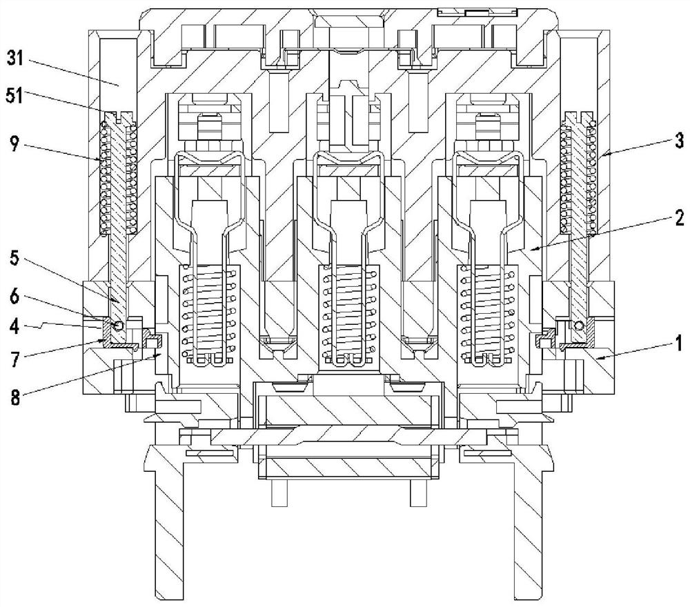
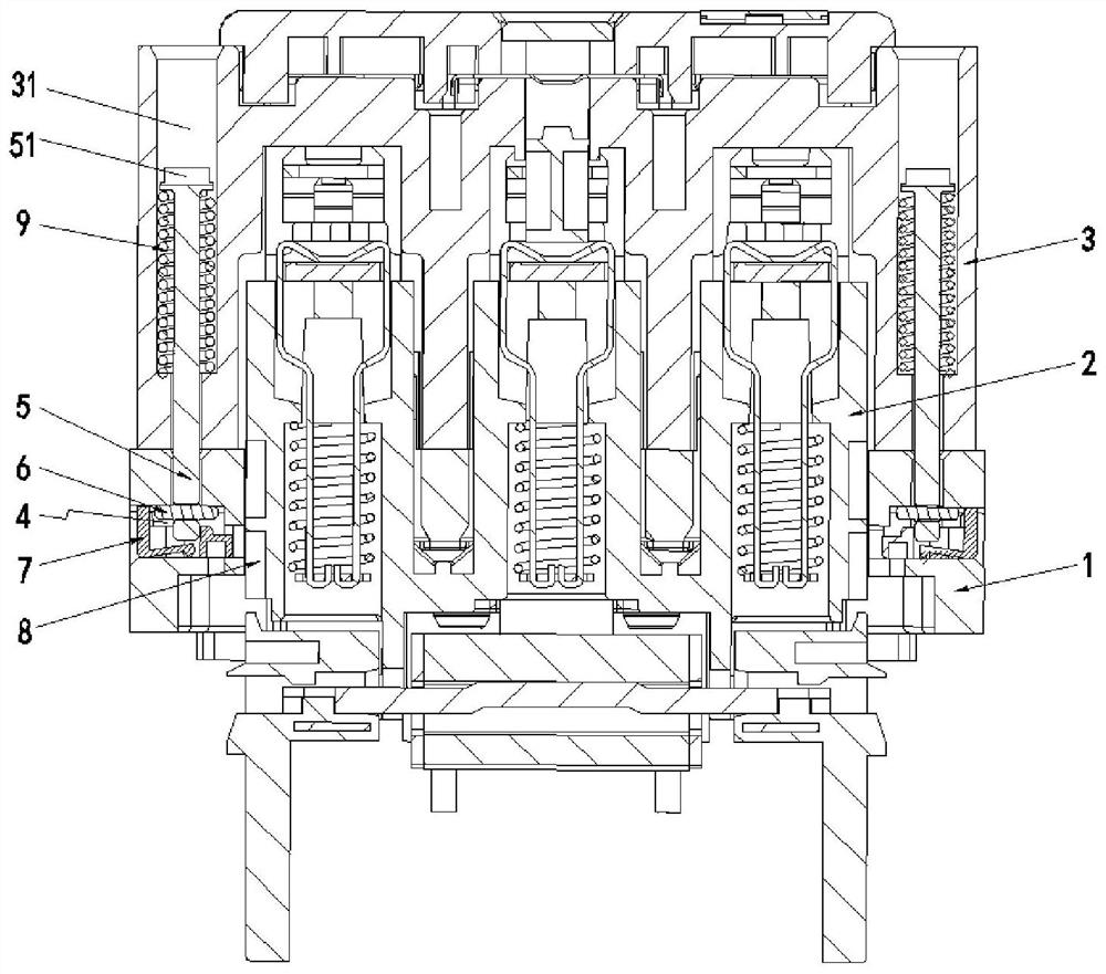
[0039] This embodiment provides as Figure 1-9 The shown contactor locking device includes a base 1, a contact support 2 and an arc extinguishing cover 3, and also includes:

[0040] The installation structure includes installation grooves 4 arranged on both sides of the top of the base 1, and an operating rod 5 which is rotated and passed between the installation groove and the arc extinguishing cover, and is arranged on the operating rod. The bottom end is suitable for inserting into the stopper 6 in the installation groove. When the stopper 6 rotates forward or reverse with the operating rod 5, it has a limit fit with the installation groove 4. To maintain the fixed position where the relative position of the base 1 and the arc chute 3 is fixed, and the detachment position where the limit fit is released from the installation groove 4;

[0041] The locking assembly includes a socket hole 11 that is provided on one or both side walls of the base 1 and communicates with the ...


PUM


Abstract

The invention discloses a contactor locking device. The device comprises a base, a contact support, an arc extinguishing cover and a locking assembly, the locking assembly comprises a slot hole, locking grooves and a locking block, the slot hole is communicated with a mounting groove in a penetrating manner, the locking grooves are formed in two side walls of the contact support and are opposite to the slot hole, the locking block can be slidably inserted between the mounting groove and the locking grooves through the slot hole, the mounting grooves are formed in the two sides of the top of the base, the arc extinguishing cover is inserted into the mounting grooves through an operating rod and a limiting part to be connected with the locking block, and when the arc extinguishing cover is in the assembling process, a limiting part is driven by the operating rod to clockwise rotate by 90 DEG to drive the locking block to slide out of the locking grooves so as to unlock the contact support; and when the arc extinguishing chamber is in the dismounting process, the limiting part is driven to rotate by 90 DEG anticlockwise through the operating rod, so that the locking block is driven to be inserted into the locking grooves in a sliding mode to achieve the locking effect on the contact support.

Description

technical field [0001] The invention relates to the technical field of low-voltage electrical appliances, in particular to a contactor locking device. Background technique [0002] As a large-scale and wide-ranging control electrical appliance, the contactor is mainly used in the control circuit to connect and break the circuit remotely and to control the starting, stopping, and breaking of the motor during operation. The contactor mainly includes a body, a base, an electromagnetic Coil assembly, arc extinguishing cover, static contact, contact support and moving contact, the static contact is installed on the body, and the moving contact is installed on the contact support, and the contact support is movably installed in the body, and in the electromagnetic The movement under the action of the coil makes the moving contact contact or separate from the static contact. [0003] Most of the existing contactors do not have self-locking function. When the active contact and the...

Claims


Application Information

Patent Timeline
Patent Type & Authority Applications(China)
IPC IPC(8): H01H50/32H01H50/02
CPCH01H50/02H01H50/32
Inventor 季勤雄许建余蔡慧茂朱家逵刘振武潘锦强王惜晨
Owner ZHEJIANG PEOPLE ELE APPLIANCE
Why Eureka
Try Eureka