Camera automatic calibration method and optical motion capture system

An automatic calibration and camera technology, which is applied to the parts of the TV system, image data processing, TV, etc., can solve the problems of camera initial installation position offset, waste of time, and affect the positional relationship of the camera, so as to improve accuracy and reduce Effects of small errors, improving accuracy and fluency

Active Publication Date: 2019-05-14
SHENZHEN REALIS MULTIMEDIA TECH CO LTD
View PDF12 Cites 22 Cited by
  • Summary
  • Abstract
  • Description
  • Claims
  • Application Information

AI Technical Summary

Problems solved by technology

[0005] However, in the application process of the optical motion capture system, there are still the following problems about camera calibration: (1) The environment in which the system operates is constantly changing, such as the temperature difference between morning and evening, which will affect the state of the camera itself, that is, the camera Internal parameters; (2) The camera installation environment will inevitably encounter vibrations, which will cause the camera to shift from the initial installation position, which will affect the positional relationship between the current cameras, that is, the camera external parameters; (3) In reality It is impossible for us to re-calibrate the camera at any time, which will waste a lot of time and greatly reduce the smoothness of the entire system

Method used


Image

  • Camera automatic calibration method and optical motion capture system
  • Camera automatic calibration method and optical motion capture system
  • Camera automatic calibration method and optical motion capture system

Examples


Embodiment 1

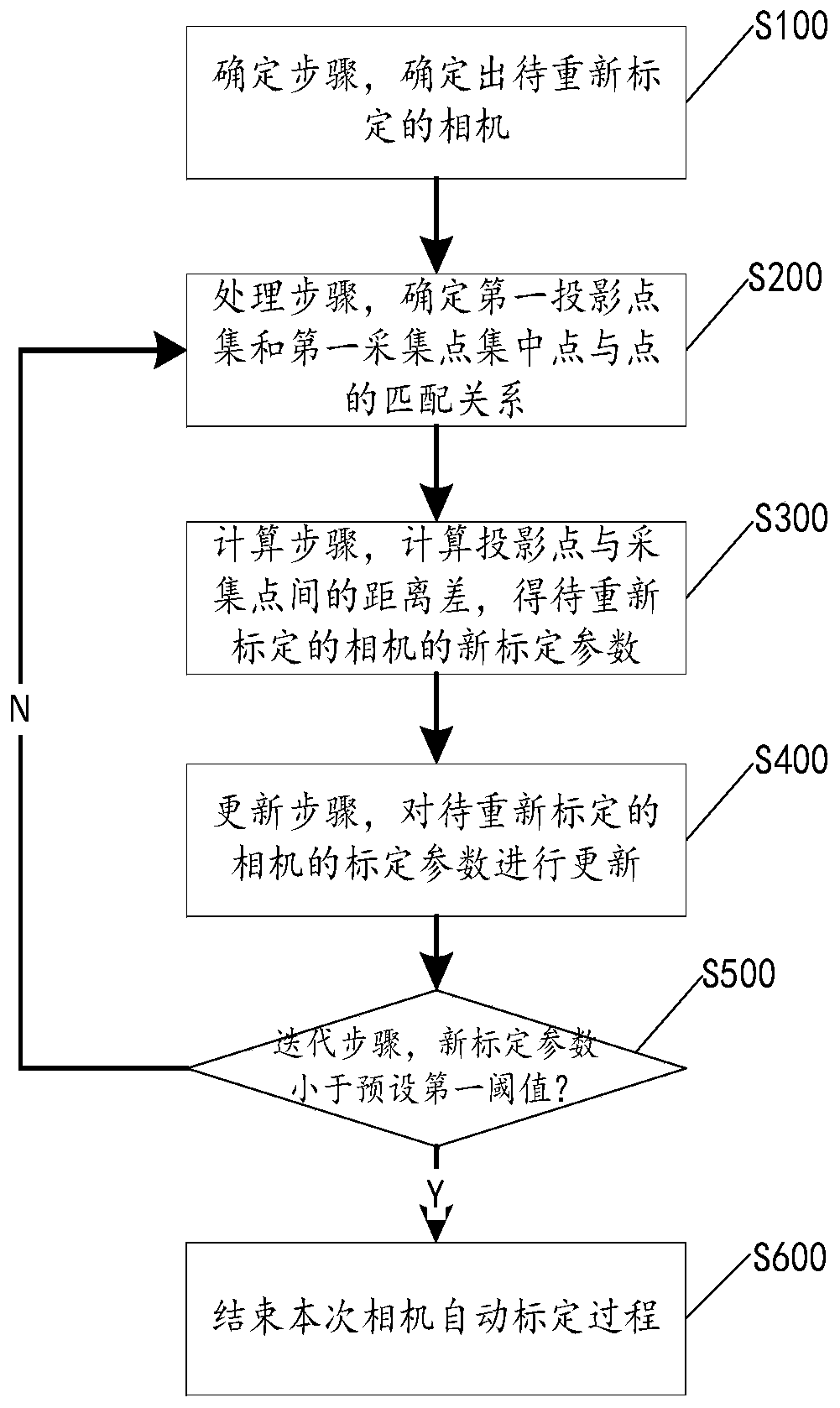
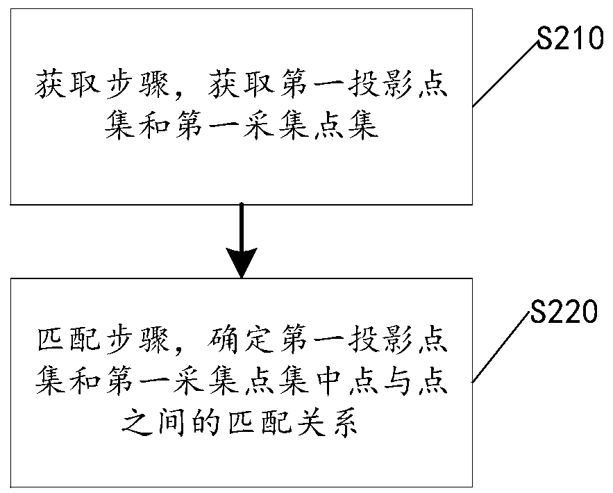
[0045] Please refer to figure 1 , the present application discloses an automatic camera calibration method for calibrating multiple cameras in a computer vision system. The camera automatic calibration method for protection includes steps S100-S400, which will be described separately below.

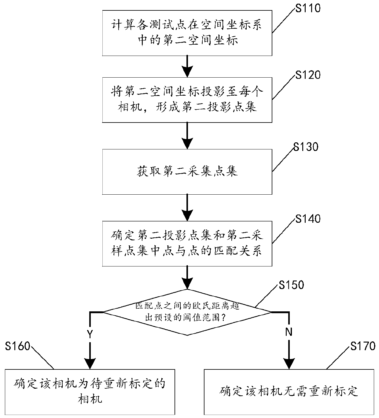
[0046] Step S100, determining step: determining the camera to be re-calibrated from multiple cameras. In an embodiment, the step S100 may include steps S110-S170, which are respectively described as follows.

[0047] Step S110, calculating the second space coordinates of each test point in the space coordinate system according to the images captured by each camera.

[0048] It should be noted that, for example, in an optical motion capture system, multiple cameras will continuously capture images of multiple test points (such as multiple points on one or more captured objects), and establish a motion space where the captured objects are located. space coordinate system (or called the w...

Embodiment 2

[0083] Please refer to Figure 6 , on the basis of the camera automatic calibration method claimed in Embodiment 1, the present application also discloses an optical motion capture system, which not only includes a plurality of test points to be captured and a plurality of cameras for taking pictures of these test points, A processor 10 is also included.

[0084] Wherein, a plurality of test points are set on one or more capturing objects 11 in the motion space, such as Figure 6 shown. A plurality of cameras (such as camera 1, camera 2,...camera i,...camera m, 1


PUM


Abstract

The invention discloses a camera automatic calibration method and an optical motion capture system. The camera automatic calibration method comprises a determination step, a processing step, a calculation step, an updating step, an iteration step and an ending step. On one hand, the camera automatic calibration method is suitable for a computer vision system. The calibration parameters of the camera can be continuously updated while the system collects the test point, the automatic calibration function is achieved by continuously optimizing the calibration state of the camera, the system can be in the optimal calibration state all the time, and therefore the accuracy and fluency of system operation are improved. And on the other hand, the camera to be calibrated again is found out throughthe determination step, so that the camera to be calibrated again is in a shielding state, the normal work of other cameras is not influenced, and the camera to be calibrated again can be supported through the normally working camera to carry out automatic camera calibration.

Description

technical field [0001] The invention relates to the technical field of camera calibration, in particular to an automatic camera calibration method and an optical motion capture system. Background technique [0002] In the image measurement process and machine vision applications, in order to determine the relationship between the three-dimensional geometric position of a point on the surface of a space object and its corresponding point in the image, it is necessary to establish a geometric model of camera imaging, and these geometric model parameters are camera parameters. Under most conditions, these parameters must be obtained through experiments and calculations. This process of solving parameters is called camera calibration (or camera calibration). [0003] For example, in the optical motion capture system, multiple cameras are used to collect optical images of moving objects. In the process of optical motion capture, the tracking and positioning software adopts the pr...

Claims


Application Information

Patent Timeline
Patent Type & Authority Applications(China)
IPC IPC(8): G06T7/80
CPCH04N17/002G06T7/80G06T2207/30244G06T2207/10028H04N23/90G06T7/97G06T7/50G06T7/70
Inventor 王越赵晓琴许秋子
Owner SHENZHEN REALIS MULTIMEDIA TECH CO LTD
Why Eureka
Try Eureka