
Reverse debugging of software failures

A hardware, destination technology, applied in the field of reverse debugging of software faults

Pending Publication Date: 2021-05-11
MICROSOFT TECH LICENSING LLC
View PDF0 Cites 0 Cited by
  • Summary
  • Abstract
  • Description
  • Claims
  • Application Information

AI Technical Summary

Problems solved by technology

Existing debug systems are indeed not able to handle this concurrency problem since inferring all possible sequencing options would require exponential branching / analysis potential

Method used


Image

  • Reverse debugging of software failures
  • Reverse debugging of software failures
  • Reverse debugging of software failures

Examples


Embodiment Construction

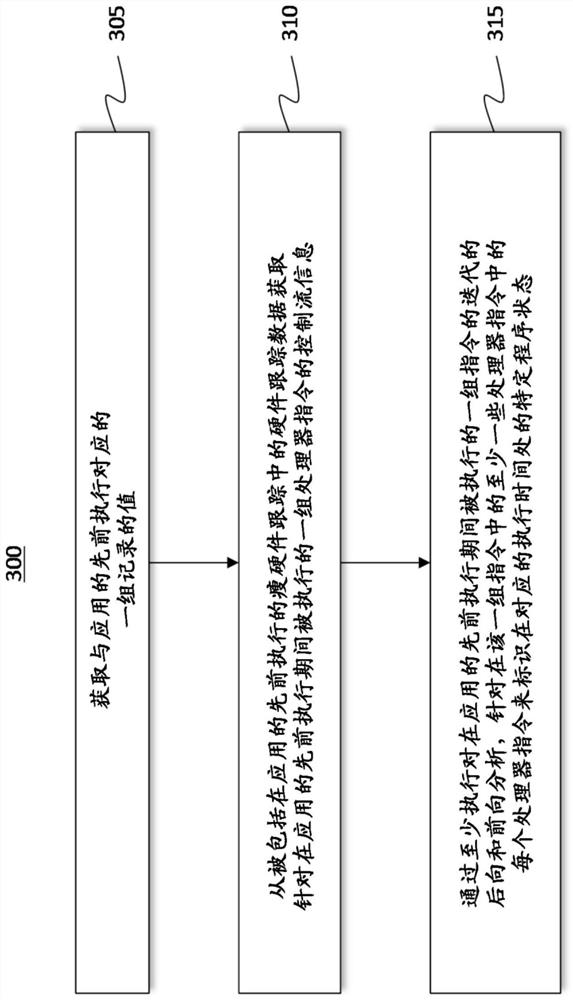
[0032] The disclosed embodiments include computer systems, methods, and hardware storage devices configured to perform time travel debugging using sparse hardware trace data (e.g., control flow data) in conjunction with a limited set of logged state values ​​in a manner that intelligently Debugging is performed in a manner that determines when to avoid making inferences that may lead to forbidden analysis, thereby mitigating memory aliasing and / or multi-thread concurrency issues.

[0033] In some embodiments, a recorded set of state values ​​corresponding to previous executions of the application is obtained, such as from a memory dump file, or as a manually triggered procedure corresponding to a breakpoint or another specified location within the code being debugged result of stopping. Control flow information describing the sequence of a set of processor instructions executed during a previous execution of the application is also obtained from hardware trace data included in...


PUM


Abstract

Debugging systems are configured to resolve both memory aliasing conditions in which a write instruction is directed to an unknown destination address, and concurrency conditions in which control flow information is collected for multiple, concurrently executing threads. Recorded state values corresponding to an application's prior execution and control flow information are both obtained.

Description

Background technique [0001] Computers and corresponding software applications are becoming more sophisticated, enabling users to store, access, and manipulate data in a variety of ways. For example, computing applications may be used to perform word processing, graphics processing, sound / visual processing, data analysis, electronic communication, and more. [0002] A computer application includes code in the form of executable instructions that are executed by one or more processors of a computer system. These instructions are created and sequenced together by the developer in the development environment. Once the instructions are compiled, interpreted and / or built, the corresponding application can be deployed for use. [0003] Unfortunately, computer systems and applications do not always operate as intended or expected, which can cause the application to crash, either before or after deployment. For at least this reason, it is often necessary to debug applications to ide...

Claims


Application Information

Patent Timeline
Patent Type & Authority Applications(China)
IPC IPC(8): G06F11/36G06F11/07
CPCG06F11/3636G06F11/3612G06F11/364G06N3/082G06N5/027G06N5/04G06F40/30G06F40/44G06F40/45
Inventor 崔伟东葛馨阳B·C·C·卡斯克西牛犇王若愚尹寅洙
Owner MICROSOFT TECH LICENSING LLC
Learn More