
Top end braking method for aisle stacker

A technology of stacker and roadway, which is applied in the direction of transportation, packaging, and storage devices, and can solve the problems of limited mechanical strength, increased production cost, and small thickness

Inactive Publication Date: 2021-05-14
QINGDAO KENGIC AUTOMATION EQUIP CO LTD
View PDF8 Cites 0 Cited by
  • Summary
  • Abstract
  • Description
  • Claims
  • Application Information

AI Technical Summary

Problems solved by technology

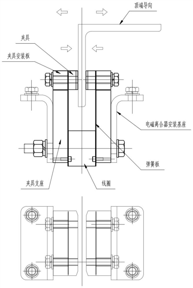
[0004] The above electromagnetic clutch makes the two magnetic conductors adsorb on both sides of the track through electromagnetic action, but because the thickness of the two spring plates connecting the magnetic conductors is small and the mechanical strength is relatively limited, it is easier to tear when braking. The use reliability and practicability cannot meet the braking requirements of existing large-scale equipment
Moreover, after long-term use, the elasticity of the spring plate weakens, and the return elastic force is difficult to meet the design requirements. The gap between the fixture and the track becomes larger, resulting in a decrease in the braking force and an increase in the braking distance. The corresponding solution can only be to replace the spring plate , the production cost increases accordingly

Method used


Image

  • Top end braking method for aisle stacker
  • Top end braking method for aisle stacker
  • Top end braking method for aisle stacker

Examples


Embodiment 1

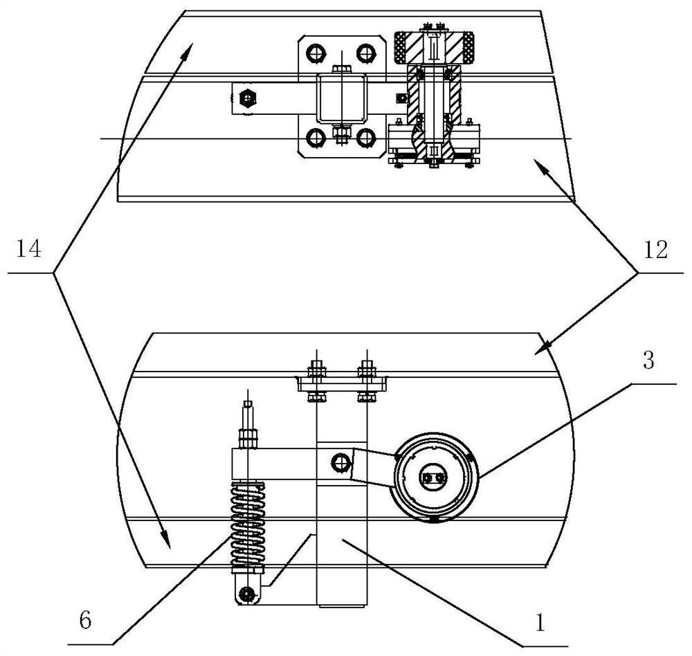
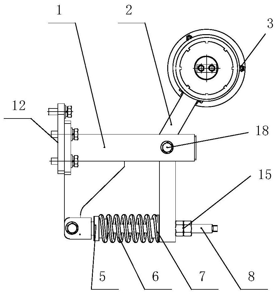
[0020] Example 1, such as Figure 1 to Figure 4 As shown, in order to realize the braking method at the top of the roadway stacker described in the present application, the bracket 1 of the braking device is fastened to the upper beam 12 of the stacker, and the middle part of the rotating arm 2 is arranged on the bracket 1 through the bolt shaft 18, and the rotation The far end of the arm 2 is welded with a pivot arm sleeve 10, and a clamp 9 is arranged on the outer periphery of the pivot sleeve 10, and the two ends of the clamp 9 are fastened to the pivot arm 2 by bolts; 1. A brake shaft 11, a roller bearing 16, and a deep groove ball bearing 17 are arranged along its axial center; on one side of the arm sleeve 10, a roller 3 is sleeved on the shaft end of the brake shaft 10, and passes through the end The cover and the bolt 13 fasten the two in the axial direction; on the other side of the pivot arm sleeve 10, a flange 19 is arranged, the shaft end of the brake shaft 10 pass...


PUM


Abstract

According to a top end braking method of an aisle stacker, which is provided by the invention, different friction modes of a roller at the shaft end of a braking shaft on the surface of a guide rail are controlled and changed through an electromagnetic clutch, so that cadence braking and continuous braking modes in a high-speed running state are achieved, and the design aims of not only improving the braking efficiency, but also giving consideration to reduction of the impact force on a goods shelf when the stacker is started up and stops are fulfilled. According to the braking method, in the process that an upper cross beam moves in the horizontal direction of the guide rail at the top end of the stacker, on-off of the electromagnetic clutch and the braking shaft is controlled through power-on and power-off, and switching between a rolling state and a sliding state of the roller on the surface of the guide rail is executed.

Description

technical field [0001] The invention relates to the improvement of a smooth braking method when the upper beam of a stacker is traveling, and belongs to the technical field of logistics storage. Background technique [0002] At present, various types of stackers are usually used in the operation and transportation site of the three-dimensional logistics storage. For the roadway stacker with a large vertical height of the shelf, when the upper beam is braked frequently and at high speed in the roadway, it is required to respond quickly and position accurately. However, due to the high equipment and heavy weight, the running inertia of the equipment is also large, which causes the upper end of the stacker to swing several times during braking before stopping, which seriously affects the efficiency of cargo transmission operations. [0003] as attached figure 1 The existing braking device shown has an overall structure consisting of a clamp support, a coil, a spring plate, a ...

Claims


Application Information

Patent Timeline
Patent Type & Authority Applications(China)
IPC IPC(8): B65G1/04
CPCB65G1/0428
Inventor 龙进军孔祥峰郭环
Owner QINGDAO KENGIC AUTOMATION EQUIP CO LTD
Learn More