
Light-emitting device capable of adjusting light rays of light source at light entering end of light guide

A light-emitting device and light-incoming technology, which is applied in the direction of light sources, signal devices, lighting devices, etc., can solve the problems of exacerbating bright spots at the end and wasting light, and achieve the effects of increasing diversity, realizing long-distance transformation, and saving vertical space

Pending Publication Date: 2021-05-14
CHANGZHOU XINGYU AUTOMOTIVE LIGHTING SYST CO LTD
View PDF0 Cites 1 Cited by
  • Summary
  • Abstract
  • Description
  • Claims
  • Application Information

AI Technical Summary

Problems solved by technology

[0003] At present, there are many forms of adding reflective surfaces to the light input end of thick-walled parts, but there are fewer forms of adding emission surfaces to the light input end of the thick-walled parts. The parallel light collimated by ordinary paraboloids is not conducive to emitting light to the light guide teeth for light output. , only a small part is used by the light guide teeth, and most of them are transmitted to the end of the light end, which will intensify the bright spots at the end; and the cross section of the light guide is generally only φ4-8mm, and the reflective surface is relatively large, which will waste a large part of the light

Method used


Image

  • Light-emitting device capable of adjusting light rays of light source at light entering end of light guide
  • Light-emitting device capable of adjusting light rays of light source at light entering end of light guide

Examples


Embodiment 1

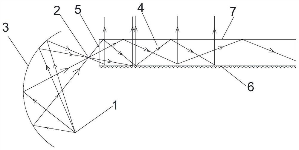
[0014] As shown in the figure, a light-emitting device for adjusting the light of the light source at the light-introducing end includes a light guide 4 and a reflective bowl 3. The reflective bowl 3 is arranged close to the light-incoming surface 5 of the light guide 4. The reflective bowl 3 has a first A focal point 1 and a second focal point 2, the first focal point 1 is provided with an LED light source, the light emitted by the LED light source enters the light guide 4 through the second focal point 2, and the first focal point 1 deviates from the The light guide 4 is set.

[0015] The reflective surface of the reflective bowl 3 is a free-form surface. The free-form surface may be an ellipsoid, a parabola or a spherical arc. The light guide 4 also includes a light-emitting surface 7 and a light-emitting structure 6 opposite to the light-emitting surface 7 , and the light-emitting structure 6 is a tooth-shaped, leather-like or dot-shaped convex structure. The distance be...

Embodiment 2

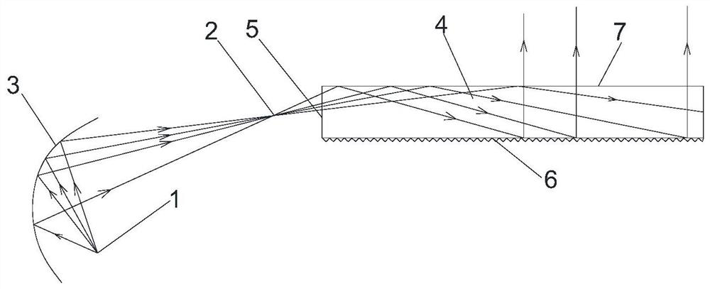
[0017] The difference from Embodiment 1 is that there is no space in the head of the light guide 4, and the light source needs to be placed in other relatively open areas, such as figure 2 As shown, the first focal point 1 is far away from the light guide 4, the reflective surface of the reflective bowl 3 is a paraboloid, the LED light source is arranged at the first focal point 1, and the light emitted by the LED light source enters the light guide 4 through the second focal point 2 Inside, the second focal point 2 is located at +2.5mm from the light entrance surface 5. Since the parabolic reflective surface is relatively large, the required part can be intercepted according to the spatial structure, and most of the light is concentrated on the half of the parabolic reflective surface where the LED is actually located. , the other half of the parabolic reflector actually receives less light from the light source.

[0018] Specific working principle: a reflective bowl 3 is in...


PUM


Abstract

The invention relates to alight-emitting device capable of adjusting the light rays of a light source at the light entering end of a light guide. The light-emitting device comprises a light guide and a reflection bowl; the reflection bowl is arranged close to the light entering face of the light guide; the reflection bowl comprises a first focus and a second focus; an LED light source is arranged at the first focus; and light emitted by the LED light source enters the light guide through the second focus. According to the light-emitting device of the invention, the design of a reflection free-form surface can change the divergence angle of a light beam, so that the spatial position transformation of the light source can be realized, the longitudinal space can be saved, and a solution is provided for the insufficient space of the head of the light guide; and a light emitting structure is adopted, so that the stereo uniform effect of the light can be improved.

Description

technical field [0001] The invention relates to a light-emitting device for adjusting the light of a light source at a light-introducing light end, and belongs to the technical field of automobile lighting. Background technique [0002] With the rapid development of automotive lighting technology, the design of car lights is becoming smaller and narrower. While the light emitting surface is enlarged, the structure of the car lights is also reduced, and the shading width of the bezel is getting smaller and smaller. There are certain requirements for space. For a structure with a small space, it is difficult to place the light source directly on the head of the light guide, and the direction of the light source needs to be adjusted. [0003] At present, there are many forms of adding reflective surfaces to the light input end of thick-walled parts, but there are fewer forms of adding emission surfaces to the light input end of the thick-walled parts. The parallel light collima...

Claims


Application Information

Patent Timeline
Patent Type & Authority Applications(China)
IPC IPC(8): F21S41/24F21S41/32F21S41/141F21W107/10F21Y115/10
CPCF21Y2115/10F21S41/141F21S41/24F21S41/32F21W2107/10
Inventor 钱茜王飞飞
Owner CHANGZHOU XINGYU AUTOMOTIVE LIGHTING SYST CO LTD
Learn More