
Laser ranging system and laser ranging device

A technology of laser ranging and light source, applied in the field of optical scanning and optical measurement

Active Publication Date: 2022-07-22
湖南阿秒光学科技有限公司
View PDF9 Cites 0 Cited by
  • Summary
  • Abstract
  • Description
  • Claims
  • Application Information

AI Technical Summary

Problems solved by technology

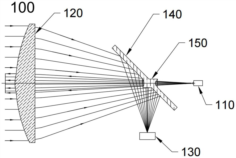
[0006] In order to overcome the deficiencies of the prior art, the present invention provides a laser distance measuring system and a laser distance measuring device to solve the problems caused by the laser emitting and receiving in the prior art. The light shares a lens, and when the position of the light source is adjusted, the focus position of the received light changes, so the adjusted position of the photosensitive chip that receives the light also needs to be adjusted twice.

Method used


Image

  • Laser ranging system and laser ranging device
  • Laser ranging system and laser ranging device
  • Laser ranging system and laser ranging device

Examples


Embodiment Construction

[0063] The technical solutions in the embodiments of the present invention will be clearly and completely described below with reference to the accompanying drawings in the embodiments of the present invention. Obviously, the described embodiments are only a part of the embodiments of the present invention, not all of the embodiments. Based on the embodiments of the present invention, all other embodiments obtained by those of ordinary skill in the art without creative efforts shall fall within the protection scope of the present invention.

[0064] It should be noted that if there are directional indications (such as up, down, left, right, front, back, etc.) involved in the embodiments of the present invention, the directional indications are only used to explain the relationship between various components in a specific posture If the specific posture changes, the directional indication also changes accordingly.

[0065] In addition, if there are descriptions involving "first...


PUM


Abstract

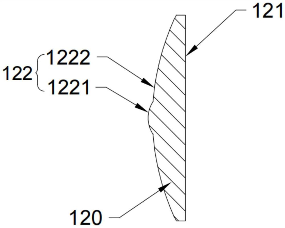
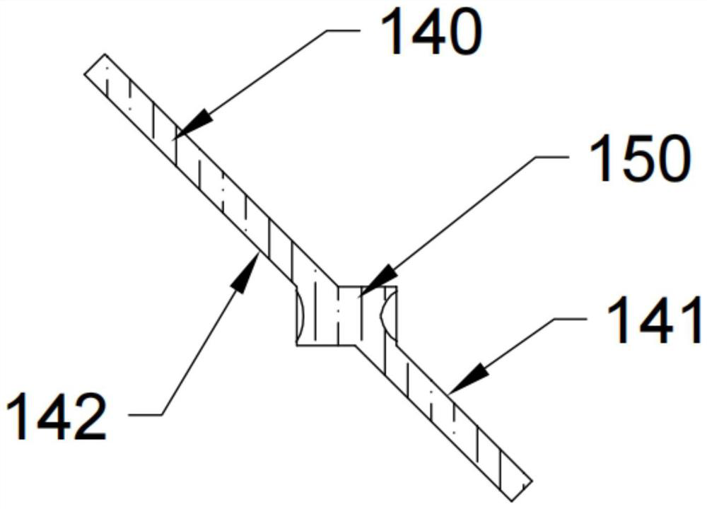
The invention discloses a laser ranging system and a laser ranging device. The first optical element comprises a first part and a second part, the first part is used for converting emitted light of the light source into collimated light, and the second part is used for converging reflected light obtained after the collimated light is reflected by a target object; the photosensitive chip is used for receiving the reflected light and outputting measurement data; a second optical element disposed between the light source and the first optical element; the beam expanding lens is embedded in the second optical element and penetrates through the second optical element, the optical axis of the beam expanding lens and the optical axis of the light source are located on the same straight line, and emitted light emitted by the light source penetrates through the beam expanding lens and enters the first optical element; and the second optical element reflects the reflected light converged by the first optical element to the photosensitive chip.

Description

technical field [0001] The invention relates to the technical field of optical measurement and optical scanning, in particular to the technical field of laser radar, and in particular to a laser ranging system and a laser ranging device. Background technique [0002] Lidar is a radar system that emits a laser beam to detect the position of a target and other characteristic quantities. The photosensitive sensor of the lidar can convert the obtained optical pulse signal into an electrical signal, and obtain the time information corresponding to the electrical signal based on the comparator, thereby obtaining the distance information between the lidar and the target. [0003] In the distance measuring device, the edge emission laser (EEL) is generally used as the light source, and the avalanche diode (APD) is used as the receiving element. [0004] When assembling the light source to the mounting seat of the laser measurement system, due to the processing deviation and install...

Claims


Application Information

Patent Timeline
IPC IPC(8): G01S17/10G01S7/481
CPCG01S17/10G01S7/481
Inventor 黄柏良
Owner 湖南阿秒光学科技有限公司
Learn More