
Annular light beam generation method based on liquid crystal phased array

A ring beam and generation method technology, applied in optics, nonlinear optics, instruments, etc., can solve problems such as system errors, difficult assembly and adjustment, and difficult processing of complex mirror groups, and achieve accurate and controllable surface shapes, simple optical systems, and The effect of low debugging difficulty

Active Publication Date: 2020-08-28
LASER FUSION RES CENT CHINA ACAD OF ENG PHYSICS
View PDF19 Cites 3 Cited by
  • Summary
  • Abstract
  • Description
  • Claims
  • Application Information

AI Technical Summary

Problems solved by technology

The traditional technology generally has the following defects: 1. Although the perfect transformation can be realized theoretically without any aberration, the complex mirror group has problems of difficult processing and assembly, and small deviations will bring obvious errors to the system
2. The mirror group designed and processed for a specific cassette system can only produce a specific annular beam that matches it. When the central blocking ratio of the cassette system changes, it is no longer applicable
3. It only transforms the geometric shape of the beam, but does not improve the laser divergence angle

Method used


Image

  • Annular light beam generation method based on liquid crystal phased array
  • Annular light beam generation method based on liquid crystal phased array

Examples


Embodiment 1

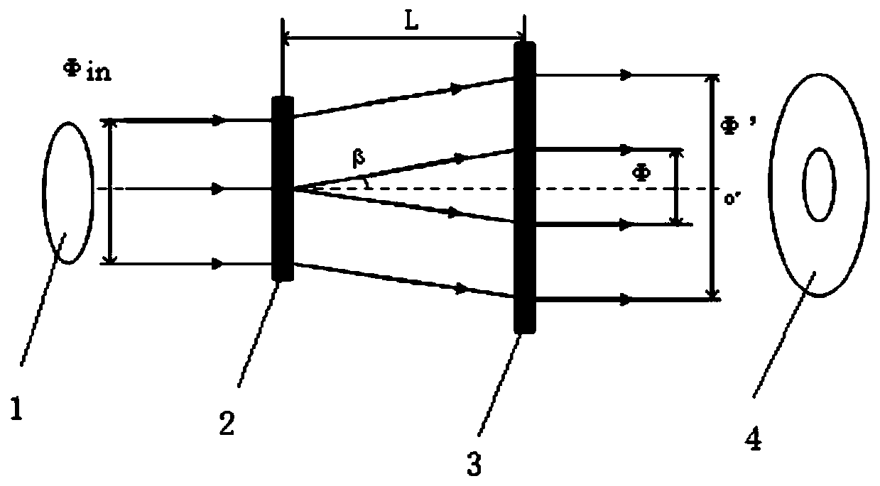
[0024] A method for generating ring beams based on a liquid crystal phased array, such as figure 1 As shown, first, through the first liquid crystal phased array 2, the incident beam 1 is conically diverged at a certain angle, deflected once to form a conical diverging beam, the incident beam 1 is a single-wavelength circular beam, and then the conical diverging beam After a certain distance is transmitted, when the diameter of the conical diverging beam becomes larger to the same outer diameter as the target annular beam 4, the conical diverging beam is reversely deflected by the second liquid crystal phased array 3, and the secondary deflection becomes hollow. Parallel light, get target ring light beam 4, output.

[0025] Wherein, the first liquid crystal phased array 2 and the second liquid crystal phased array 3 are spaced apart and placed in parallel, and both of them are transmissive phase modulation liquid crystal phased arrays, and the first liquid crystal phased array...


PUM


Abstract

The invention relates to an annular light beam generation method based on a liquid crystal phased array, which belongs to the technical field of light beam shaping, and comprises the following steps:determining the inner diameter and the outer diameter of a target annular light beam; enabling the first liquid crystal phased array to perform primary deflection on the incident light beam to form aconical divergent light beam; and when the diameter of the conical divergent light beam is the same as the outer diameter of the target annular light beam, using the second liquid crystal phased arrayfor carrying out secondary deflection on the conical divergent light beam, and obtaining a target ring beam. The optical system is simple, related devices are mature in technology, compared with a traditional geometric transformation technology, the advantages of low debugging difficulty, accurate and controllable surface shape and the like are realized, meanwhile, by applying programmable control driving voltage to the first liquid crystal phased array and the second liquid crystal phased array, the deflection angle value can be conveniently, flexibly, precisely and dynamically controlled, and then the divergence angle, the inner diameter and the outer diameter of the target annular light beam are changed so as to meet the requirements of different types of card type systems for the annular light beam.

Description

technical field [0001] The invention belongs to the technical field of beam shaping, and in particular relates to a method for generating an annular beam based on a liquid crystal phased array. Background technique [0002] The Cassegrain telescope launch system (cassette system for short) is often used in high-power large-aperture laser launch systems due to its advantages of compact structure, easy realization of large-aperture beam expansion, no chromatic aberration, and high reflection efficiency. However, in the cassette system, since the secondary mirror is located in the emission path of the primary mirror, and there is a ring in the center of the primary mirror, when used for beam expansion, the incident circular beam will become a ring beam after passing through the beam expander , the central obscuration in the launch system. On the one hand, central occlusion will waste the most concentrated part of energy and make it unable to function. On the other hand, the oc...

Claims


Application Information

Patent Timeline
Patent Type & Authority Applications(China)
IPC IPC(8): G02F1/29G02F1/133
CPCG02F1/292G02F1/13306
Inventor 王德恩杨英张鑫邓学伟王芳陈良明许党朋郑胜亨李明中郭雨源廖予祯袁强袁晓东胡东霞
Owner LASER FUSION RES CENT CHINA ACAD OF ENG PHYSICS
Learn More