Gearbox shaft rotating speed position sensor fixing device

A fixed device and sensor technology, applied in the field of gearboxes, can solve problems such as unfavorable detection efficiency, poor compatibility, and prolonging the detection time of gearbox shaft speed

Inactive Publication Date: 2021-05-14
张雪梅
View PDF1 Cites 0 Cited by
  • Summary
  • Abstract
  • Description
  • Claims
  • Application Information

AI Technical Summary

Problems solved by technology

[0004] There are many types of gearboxes, and the sensor fixing device is not compatible with different sizes of gearboxes. Different gearboxes require differen...

Method used


Image

  • Gearbox shaft rotating speed position sensor fixing device
  • Gearbox shaft rotating speed position sensor fixing device
  • Gearbox shaft rotating speed position sensor fixing device

Examples


Embodiment Construction

[0025] The following will clearly and completely describe the technical solutions in the embodiments of the present invention with reference to the accompanying drawings in the embodiments of the present invention. Obviously, the described embodiments are only some, not all, embodiments of the present invention.

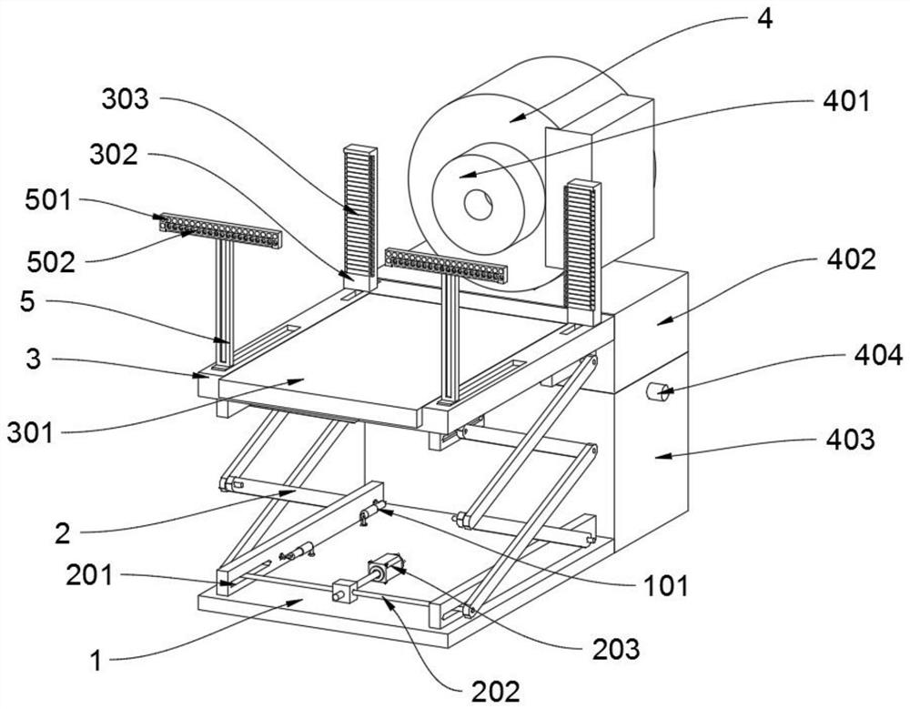
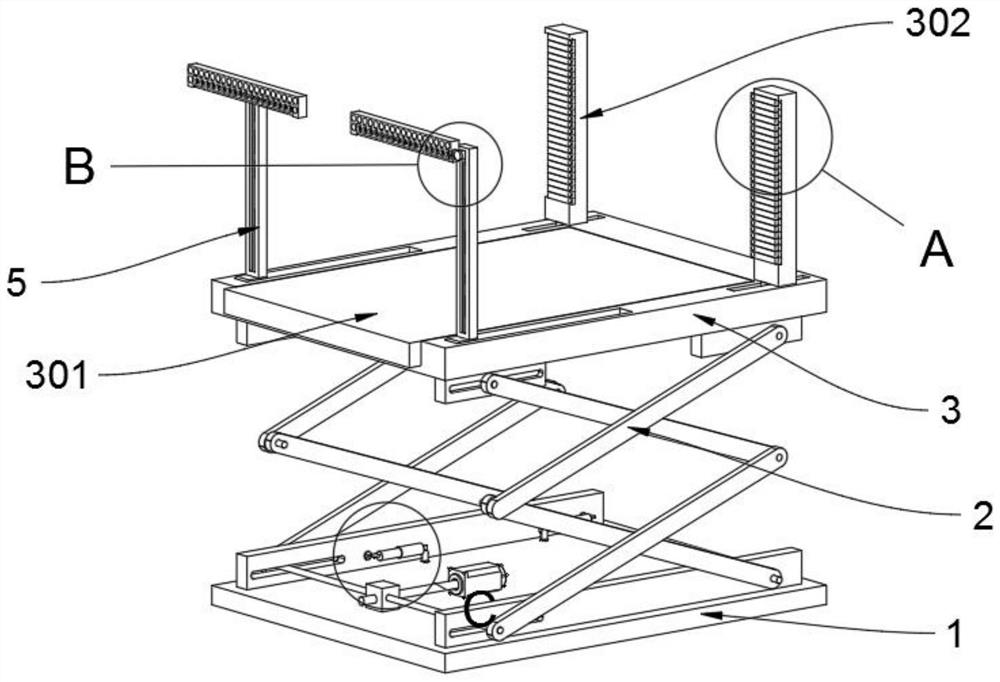
[0026] see Figure 1 to Figure 6 , an embodiment provided by the present invention: a gearbox shaft speed position sensor fixing device, including a base 1; the base 1 includes a buffer column 101 and a connecting block 102, and the top of the base 1 is rotatably connected to a connecting block 102; the buffer column 101 A buffer spring is arranged inside, and both ends of the buffer column 101 are rotatably connected with a connection block 102, and the head end of the buffer column 101 is rotatably connected with the lower support bar 201 through the connection block 102, and the vibration during detection is reduced through the buffer column 101; the connection blo...


PUM


Abstract

The invention discloses a gearbox shaft rotating speed position sensor fixing device, which relates to the technical field of gearboxes, and solves the problem that a sensor fixing device is poor in compatibility with gearboxes of different sizes. The gearbox shaft rotating speed position sensor fixing device comprises a base. The base comprises a buffer column and a connecting block, and the top of the base is rotationally connected with the connecting block; the connecting block is rotationally connected with the buffer column; the top of the base is slidably connected with a shear fork frame; the shear fork frame comprises lower supporting strips, and the bottom end of the shear fork frame is connected with one lower supporting strip in a sliding mode; the top of the shear fork frame is slidably connected with a fixing seat; the fixing seat comprises a sliding seat, a fixing column and a fixing strip, and the sliding seat is slidably connected to the middle of the fixing seat; and the top of the fixing seat is slidably connected with a fixing column. The compatibility of different gearbox fixing hole sites is enhanced through the slidable fixing strips and the supporting seats.

Description

technical field [0001] The invention relates to the technical field of gearboxes, in particular to a fixing device for a gearbox shaft rotational speed position sensor. Background technique [0002] The gearbox is a very important part of the vehicle. It can change the transmission ratio and expand the torque and speed of the driving wheels. Transmissions are divided into manual transmissions and automatic transmissions. Manual transmissions are mainly composed of gears and shafts, which generate variable speed and torque through different gear combinations; while automatic transmissions AT are composed of hydraulic torque converters, planetary gears and hydraulic pressure. The control system is composed of hydraulic transmission and gear combination to achieve variable speed and torque. After the gearbox is assembled, it will be tested by the speed and position sensor at the factory. [0003] For example, the patent No. CN208888265U discloses a gearbox shaft speed position...

Claims


Application Information

Patent Timeline
IPC IPC(8): G01P1/00G01P3/00G01M13/02
CPCG01M13/02G01P1/00G01P3/00
Inventor 张雪梅
Owner 张雪梅
Why Eureka
Try Eureka