System and method for testing large signal index of amplitude limiter chip

A test system and limiter technology, which is applied in the direction of electronic circuit testing, instruments, and measuring electronics, can solve the problems of affecting the signal transmission of the previous stage circuit, affecting the accuracy of the limiter chip, and having too many test instruments.

Inactive Publication Date: 2021-05-14
WUHAN UNIV
View PDF11 Cites 0 Cited by
  • Summary
  • Abstract
  • Description
  • Claims
  • Application Information

AI Technical Summary

Problems solved by technology

The small-signal index test method is relatively simple and accurate, and the limiter can be tested by microwave probe station and vector network analyzer, while the test of large-signal index is more complicated, and it is easy to cause errors in test results
[0003] The characteristics of the test of the large signal index of the limiter chip are: many test instruments, many adapters, complicated connections, etc.
The traditional limiter chip large-signal test scheme directly connects the limiter chip to the power amplifier for testing. This test method is not only complicated in steps, difficult to calibrate, but also has many problems: the signal of the power amplifier will be affected by the subsequent circuit. The actual output power of the power amplifier cannot be monitored in real time, and the power reflected by the limiter affects the signal transmission of the previous circuit. These problems greatly affect the accuracy of the large signal index test of the limiter chip
At the same time, the chip area of ​​the limiter is small, and the connection is difficult, which makes it very difficult to test the large signal index of the limiter chip.

Method used


Image

  • System and method for testing large signal index of amplitude limiter chip
  • System and method for testing large signal index of amplitude limiter chip
  • System and method for testing large signal index of amplitude limiter chip

Examples


Embodiment Construction

[0018] The following will clearly and completely describe the technical solutions in the embodiments of the present invention in combination with the embodiments of the present invention. Obviously, the described embodiments are only some of the embodiments of the present invention, not all of them. Based on the embodiments of the present invention, all other embodiments obtained by persons of ordinary skill in the art without making creative efforts belong to the protection scope of the present invention.

[0019] It should be noted that, in the case of no conflict, the embodiments of the present invention and the features in the embodiments can be combined with each other.

[0020] The present invention will be further described below in conjunction with specific examples, but not as a limitation of the present invention.

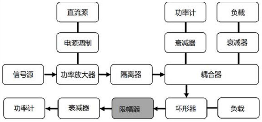
[0021] This embodiment provides a test system and method for a large signal index of a limiter chip, which can avoid test errors, and can monitor the out...


PUM


Abstract

The invention relates to the field of amplitude limiter chip testing, in particular to a sstem and method for testing a large signal index of an amplitude limiter chip. The system comprises a signal source, a power amplifier, an isolator, a coupler, a power source modulator and a direct current source; the power amplifier, the isolator, and the coupler are successively connected; and the power source modulator and the direct current source are successively connected with the power amplifier. Besides, the system also includes a first attenuator, a second attenuator and a circulator that are respectively connected with the coupler, the first attenuator is connected with a first power meter, the second attenuator is connected with a first load, the circulator is connected with a second load; and the system also includes an amplitude limiter chip testing device, a third attenuator and a second power meter that are sequentially connected with the circulator. The system is convenient to install, uniform in interface and easy to use, solves the problem that the connection of the amplitude limiter chip is difficult and the test cannot be carried out, and can enable the test of the large signal index of the amplitude limiter chip to be carried out smoothly.

Description

technical field [0001] The invention belongs to the field of limiter chip testing, in particular to a testing system and method for a large signal index of a limiter chip. Background technique [0002] Limiter indicators include small signal indicators and large signal indicators. The small-signal index test method is relatively simple and accurate, and the limiter can be tested by microwave probe station and vector network analyzer, while the test of large-signal index is more complicated, and it is easy to cause errors in test results. [0003] The characteristics of the test of the large signal index of the limiter chip are: many test instruments, many adapters, and complicated connections. The traditional limiter chip large-signal test scheme directly connects the limiter chip to the power amplifier for testing. This test method is not only complicated in steps, difficult to calibrate, but also has many problems: the signal of the power amplifier will be affected by the...

Claims


Application Information

Patent Timeline
Patent Type & Authority Applications(China)
IPC IPC(8): G01R31/28
CPCG01R31/2832
Inventor 李世峰马丽筠雷骁王雷阳邬邦
Owner WUHAN UNIV
Why Eureka
Try Eureka