
Positive and negative stiffness parallel quasi-zero stiffness vibration isolator

A technology of quasi-zero stiffness, positive and negative stiffness, applied in the field of mechanical engineering vibration isolation and vibration reduction, can solve the problems of low-frequency vibration isolation, instability, large static deformation, etc., to broaden the vibration isolation frequency band, improve stability, and reduce inherent The effect of frequency

Active Publication Date: 2018-10-16
SHANGHAI UNIV
View PDF6 Cites 22 Cited by
  • Summary
  • Abstract
  • Description
  • Claims
  • Application Information

AI Technical Summary

Problems solved by technology

When the external disturbance frequency is greater than the natural frequency of the vibration isolation system in the traditional linear passive vibration isolation system It plays a role of vibration reduction at multiple times, but for low-frequency (such as 2Hz) vibration isolation, it will encounter problems of excessive static deformation and instability during implementation, resulting in low-frequency vibration isolation problems

Method used


Image

  • Positive and negative stiffness parallel quasi-zero stiffness vibration isolator
  • Positive and negative stiffness parallel quasi-zero stiffness vibration isolator
  • Positive and negative stiffness parallel quasi-zero stiffness vibration isolator

Examples


Embodiment Construction

[0025] The following will clearly and completely describe the technical solutions in the embodiments of the present invention with reference to the accompanying drawings in the embodiments of the present invention. Obviously, the described embodiments are only some, not all, embodiments of the present invention. Based on the embodiments of the present invention, all other embodiments obtained by persons of ordinary skill in the art without making creative efforts belong to the protection scope of the present invention.

[0026] The purpose of the present invention is to provide a quasi-zero stiffness vibration isolator with positive and negative stiffness in parallel, which can realize ultra-low frequency vibration isolation.

[0027] In order to make the above objects, features and advantages of the present invention more comprehensible, the present invention will be further described in detail below in conjunction with the accompanying drawings and specific embodiments.

[0...


PUM


Abstract

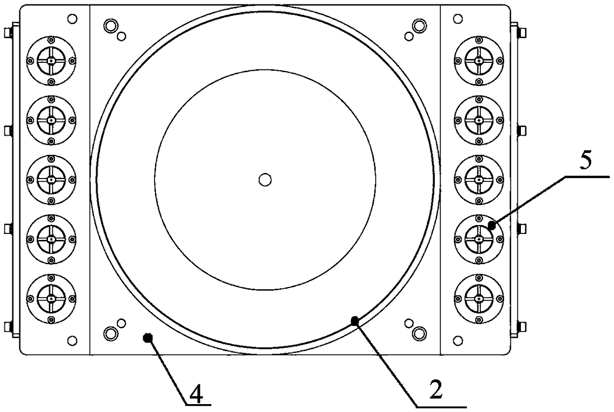
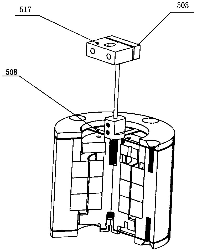
The invention discloses a positive and negative stiffness parallel quasi-zero stiffness vibration isolator which comprises an upper top plate, a lower top plate, a positive stiffness element and multiple negative stiffness elements, wherein the positive stiffness element and the multiple negative stiffness elements are located between the upper top plate and the lower bottom plate. The positive stiffness element is installed on a base plate, the base plate is fixed to the lower bottom plate and used for adjusting the height of the positive stiffness element, and the multiple negative stiffnesselements are evenly distributed on the left side and the right side of the positive stiffness element. In each negative stiffness element, an inner magnetic ring set and an outer magnetic ring set are both located in a magnetic ring sleeve, the magnetic ring sleeve is fixed to the lower bottom pate, a magnetic ring shaft is located in the axial center of the magnetic ring sleeve, the magnetic ring shaft is fixedly sleeved with the inner magnetic ring set, the inner magnetic ring set is sleeved with the outer magnetic ring set, the outer magnetic ring set is fixed to the magnetic ring sleeve,the top end of the magnetic ring shaft is connected with a metal pulling and pressing rod, the metal pulling and pressing rod is coaxial with the magnetic ring shaft, a pulling and pressing rod pressing block is fixed to the top end of the metal pulling and pressing rod and fixed to the upper top plate, and the inner magnetic ring set and the outer magnetic ring set are axially magnetized. The vibration isolator can achieve ultra-low-frequency vibration isolation.

Description

technical field [0001] The invention relates to the technical field of mechanical engineering vibration isolation and vibration reduction, in particular to a quasi-zero stiffness vibration isolator with positive and negative stiffness connected in parallel. Background technique [0002] In production practice and engineering applications, vibration often causes harmful effects and reduces the performance of the machine. When dealing with unwanted vibration problems, vibration isolation techniques are often the preferred method. When the external disturbance frequency is greater than the natural frequency of the vibration isolation system in the traditional linear passive vibration isolation system It plays the role of vibration reduction at multiple times, but for low-frequency (such as 2Hz) vibration isolation, it will encounter problems of excessive static deformation and instability during implementation, resulting in low-frequency vibration isolation problems. Conten...

Claims


Application Information

Patent Timeline
IPC IPC(8): F16F6/00
Inventor 孙翊谢荣庆杨毅蒲华燕彭艳王敏罗均谢少荣刘媛媛
Owner SHANGHAI UNIV
Learn More