Non-linear press-rod spring device

A spring device and nonlinear technology, applied in the field of spring devices, can solve the problems of stability of vibration isolation system, reduce system vibration isolation bandwidth, unfavorable popularization and application, etc., achieve low dynamic stiffness, improve internal resonance frequency, and work reliably. Effect

Inactive Publication Date: 2007-03-28
HARBIN INST OF TECH
View PDF0 Cites 16 Cited by
  • Summary
  • Abstract
  • Description
  • Claims
  • Application Information

AI Technical Summary

Problems solved by technology

For a long time, there have been great difficulties in the development of ultra-low frequency vertical vibration isolation systems, because in order to make the vibration isolation system have a very low natural frequency, the load spring of the vibration isolation system must have extremely low stiffness, because in the vertical vibration isolation system The elastic force of the load spring must be used to counteract the effect of the gravity of the vibration isolator. Therefore, the load spring has a large deformation space in the vertical direction, which will bring stability problems to the vibration isolation system on the one hand; The vibration system produces a standing wave effect at a higher frequency, reducing the vibration isolation bandwidth of the system
[0003] At present, air springs are usually used in occasions with strict vibration isolation requirements. However, air springs require auxiliary air sources, complex structures, and high overall cost, which is not conducive to popularization and application, and its natural frequency is difficult to be lower than 2Hz. Therefore, there are It is necessary to develop a new type of nonlinear spring device suitable for low frequency environment

Method used


Image

  • Non-linear press-rod spring device
  • Non-linear press-rod spring device
  • Non-linear press-rod spring device

Examples


specific Embodiment approach 1

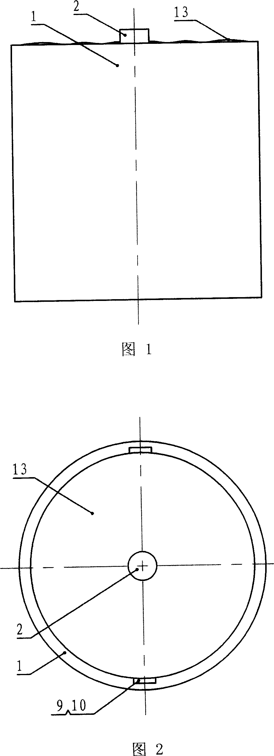
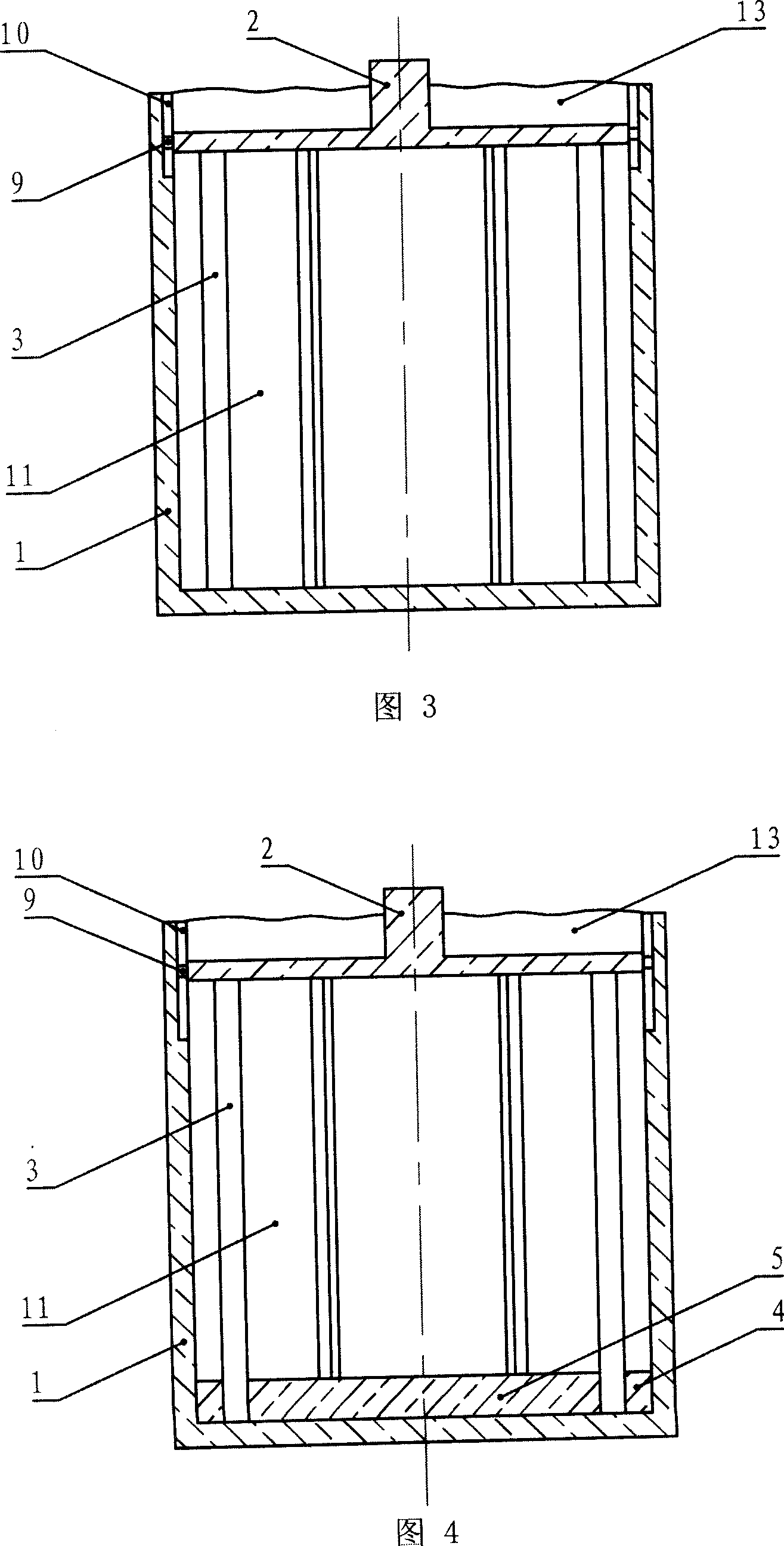
[0011] Specific embodiment 1: Referring to Fig. 3, the non-linear pressure bar spring device of the present embodiment is composed of a spring outer cover 1, an upper end cover 2, a pressure bar 3, a guide slider 9 and a guide groove 10, and the spring outer cover 1 is bottomed. The shell of the cylindrical non-linear pressure bar spring device; the upper end cover 2 is parallel to the bottom surface of the spring outer shell 1, and is embedded in the spring outer shell 1 with clearance fit, with a protruding disc in the center of the upper part; there are at least three pressure bars 3, The pressure rod 3 is evenly distributed along the circumference of the upper end cover 2, perpendicular to the bottom surface of the spring outer cover 1, and the two ends are fixedly installed on the bottom of the spring outer cover 1 and the lower surface of the upper end cover 2 respectively; there are at least two guide grooves 10, which are in the spring The upper part of the inner wall o...

specific Embodiment approach 2

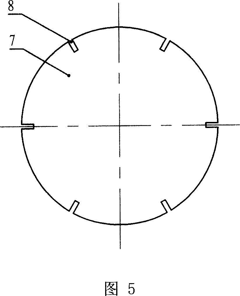
[0013] Specific embodiment two: Referring to Fig. 4, the difference between the non-linear pressure bar spring device of this embodiment and specific embodiment one is that it also includes a lower fixed collar 4 and a lower fixed disc 5, and the lower fixed collar 4 is The diameter is equal to the upper end cover 2, and it is fixedly installed on the bottom surface of the inner side of the spring jacket 1, and has a certain thickness; The ring 4 has the same thickness and is evenly opened with a number of thin grooves 8 along its circumference; one end of the pressure rod 3 is inserted into the thin groove 8 of the lower fixed disk 5, and the other end of the pressure rod 3 is fixedly installed on the upper end cover 2 .

[0014] The compression rod 3 in the non-linear compression rod spring device of this embodiment adopts an installation method of fixed connection at one end and insertion at the other end, which makes the assembly of the present invention easier.

specific Embodiment approach 3

[0015] Specific embodiment three: Referring to Fig. 6, the difference between the non-linear pressure bar spring device of this embodiment and the specific embodiment two is that it also includes an upper fixed collar 6, an upper fixed disc 7, and an upper fixed collar 6 and an upper fixed collar 6. The lower fixing collar 4 has the same shape, and the upper fixing collar 6 and the upper end cover 2 are concentrically fixedly connected on the lower surface of the upper end cover 2; the upper fixing disc 7 has the same shape as the lower fixing disc 5, and the upper fixing disc 7 is embedded in the upper The interior of the fixed collar 6 is fixedly installed on the lower surface of the upper end cover 2; the two ends of the pressure rod 3 are respectively inserted into the thin grooves 8 of the upper fixed disc 7 and the lower fixed disc 5.

[0016] The compression rod 3 in the non-linear compression rod spring device of this embodiment adopts a connection mode of plugging at b...


PUM


Abstract

This invention relates to a non-linear pressure bar spring device including a wrap, a top cover, pressure bars, guiding blocks and guiding grooves, in which, the spring wrap is a shell of a cylindrical non-linear pressure-bar spring device with a bottom, the top cover is a disk with a hump at the top center and parallel to the bottom of the spring wrap and inserted into the wrap , the pressure bars are distributed uniformly along the circle of the top cover, vertical to the bottom of the wrap with both ends mounted on the bottom of the wrap and the lower surface of the top cover, the guiding grooves are several grooves opened vertically and uniformly at the upper part of the inside wall of the wrap and the guiding blocks are mounted on the side wall of the top cover corresponding to the positions of the grooves and inserted in the grooves separately.

Description

technical field [0001] The invention relates to a spring device. Background technique [0002] With the development of science and technology, all kinds of precision equipment have more and more stringent requirements for isolating the ultra-low frequency broadband of the external environment. For example, in ultra-precision machining, it is required to isolate the vibration of the external environment between 0.5Hz and 70Hz. For a long time, there have been great difficulties in the development of ultra-low frequency vertical vibration isolation systems, because in order to make the vibration isolation system have a very low natural frequency, the load spring of the vibration isolation system must have extremely low stiffness, because in the vertical vibration isolation system The elastic force of the load spring must be used to counteract the effect of the gravity of the vibration isolator. Therefore, the load spring has a large deformation space in the vertical direction,...

Claims


Application Information

Patent Timeline
Patent Type & Authority Applications(China)
IPC IPC(8): F16F7/00F16F15/02
Inventor 陈明君张建卓梁迎春李旦董申
Owner HARBIN INST OF TECH
Why Eureka
Try Eureka