
Map construction method based on low-cost vehicle-mounted 2D lidar

A two-dimensional laser radar and map construction technology, which is applied in the directions of electromagnetic wave re-radiation, instruments, and measuring devices, can solve problems such as unreliability, low execution efficiency, and large image data volume, and achieve low equipment installation costs The effect of reducing cumulative errors and simplifying the processing process

Active Publication Date: 2021-07-13
SOUTHWEST JIAOTONG UNIV
View PDF19 Cites 0 Cited by
  • Summary
  • Abstract
  • Description
  • Claims
  • Application Information

AI Technical Summary

Problems solved by technology

Although the measurement accuracy of this method is high, the measurement operation process is not safe, the execution efficiency is low, and it is not convenient for large-scale promotion and use.
[0008] The combined measurement method of 3D laser radar and inertial device has high measurement accuracy, but the 3D laser radar is expensive, the data volume is large, the data processing process is complicated, it is difficult to meet the real-time performance, and the sensor calibration and time synchronization are more complicated, so it is more suitable The requirement is the construction of 3D maps
[0009] The visual odometry method is to determine the position and attitude of the camera by matching adjacent time series images, so as to construct the map, but the sensor of this method is greatly affected by the ambient light and texture, so it does not have good reliability, and the image The amount of data is large, the data processing process is complex, and it is difficult to meet real-time performance

Method used


Image

  • Map construction method based on low-cost vehicle-mounted 2D lidar
  • Map construction method based on low-cost vehicle-mounted 2D lidar
  • Map construction method based on low-cost vehicle-mounted 2D lidar

Examples


Embodiment 1

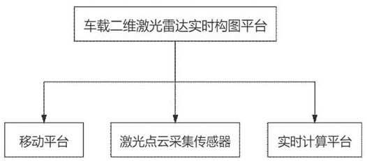
[0083] See attached figure 1 : A map construction method based on low-cost vehicle-mounted two-dimensional lidar, including the following steps:

[0084] Step S1, analyzing data:

[0085] Obtain the current frame scanning point cloud of the 2D lidar scanning output; analyze the coordinate system of multiple scanning points and the current frame scanning point cloud from the current frame scanning point cloud;

[0086]Step S2, setting the reference coordinate system of the global point cloud map;

[0087] Step S3, initialize the global point cloud map:

[0088] When the scanned point cloud of the current frame is obtained as the scanned point cloud of the first frame, the feature points are obtained from the scanned points of the scanned point cloud of the first frame, and the scanned points and feature points of the scanned point cloud of the first frame are imported into the global point cloud map The initial global point cloud map is formed in the coordinate system; the f...


PUM


Abstract

The invention discloses a map construction method based on low-cost vehicle-mounted two-dimensional laser radar, which sets the reference coordinate system of the global point cloud map; when the current frame scanning point cloud is the first frame scanning point cloud, the point cloud is scanned from the first frame The feature points are obtained from the scanned points, and the scanned points and feature points of the first frame scanned point cloud are imported into the coordinate system of the global point cloud map to form an initialized global point cloud map; the feature points of the scanned point cloud of the first frame are used as the initialized global points The global feature points of the cloud map, the scanning point of the first frame scanning point cloud is used as the fusion point for initializing the global point cloud map; when the subsequent scanning point cloud of the current frame is obtained, the front-end fusion global feature point matching method is used to integrate the scanning point of the subsequent current frame After the feature points of the cloud are transformed into the reference coordinate system, they are fused with the global feature points of the last updated global point cloud map. The fusion point is used for fusion.

Description

technical field [0001] The invention relates to the field of map construction, and mainly relates to a map construction method based on low-cost vehicle-mounted two-dimensional laser radar. Background technique [0002] The real-time development of technologies such as mobile Internet and smart sensors has promoted the popularization of location-based service-related applications. The positioning research in large-scale indoor building spaces such as underground parking lots, shopping centers, hospitals, and airports has become a research hotspot in indoor location-based services. [0003] In recent years, map-assisted indoor positioning technology has attracted widespread attention. This technology achieves more accurate and stable indoor positioning by adding planar map constraints. The perception of indoor environment and the construction of indoor planar map are an indispensable part of indoor navigation and positioning. [0004] For the problem of indoor map construct...

Claims


Application Information

Patent Timeline
Patent Type & Authority Patents(China)
IPC IPC(8): G01S17/894
CPCG01S17/894
Inventor 周乐韬徐胡超
Owner SOUTHWEST JIAOTONG UNIV
Learn More