
Load shedding control method and device

A control method and load shedding technology, applied in the direction of power network operating system integration, information technology support system, climate sustainability, etc., can solve problems such as lack of versatility, poor product versatility, and complexity

Pending Publication Date: 2021-05-14
XUJI GRP +2
View PDF3 Cites 0 Cited by
  • Summary
  • Abstract
  • Description
  • Claims
  • Application Information

AI Technical Summary

Problems solved by technology

In fact, due to the lack of uniform industry standards and poor product versatility, the safety and stability control device has become the most complex and non-commercial device in the automatic control device of the power system

Method used


Image

  • Load shedding control method and device
  • Load shedding control method and device
  • Load shedding control method and device

Examples


Embodiment Construction

[0035]In order to make the objects, technical solutions, and advantages of the present invention, the present invention will be further described in detail below with reference to the accompanying drawings. It should be understood that these descriptions are merely exemplary and are not to limit the scope of the invention. Further, in the following description, a description of known structures and techniques is omitted to avoid unnecessary obscuring the concepts of the present invention.

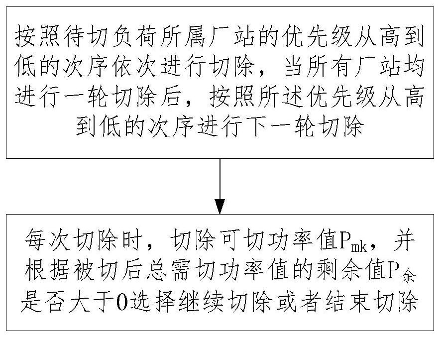
[0036]The technical solutions of the present invention will be described in detail below with reference to the drawings. According to an embodiment of the present invention, a cut load control method is provided, and the flow chart of this method isfigure 1 As shown, including:

[0037]According to the priority of the plant to be cut, it is sequentially removed from the high to low order, and the number of factory stations and rounds of the load belongs are obtained in accordance with the number of fac...


PUM


Abstract

The invention relates to a load shedding control method and device. Load shedding turns are combined with plant-station priorities to perform load shedding control, a load shedding strategy can be dynamically executed according to different access load turns and plant-station numbers, selective shedding is performed from the first turn of each plant station one by one according to the plant-station priorities, according to whether the residual value P of the total to-be-shed power value after shedding is greater than 0, continuing shedding or ending shedding is selected until the requirement of the to-be-shed power value is met, and different load shedding configuration strategies can be realized. According to the load shedding technical scheme of the invention, different requirements of different application scenes on strategies are met, and the flexibility and universality requirements of the device on the strategy function can be ensured to a great extent.

Description

Technical field[0001]The present invention relates to the field of safety and stable control technology of power systems, and more particularly to a cut load control method and apparatus.Background technique[0002]With the rapid development of the special high pressure, the grid "strong weakness" characteristics, wind power and photovoltaic and photovoltaic network capacity continue to grow, the grid pattern is significantly changed, the power supply structure is profound, in order to protect the power grid Safety and stable operation, the role of security and stability control devices is increasingly important, and applications are increasingly wide.[0003]Due to the difference in the actual situation of the power grid in different regions, the architecture and functionality of the grid of different regions were caused. For safety stability control devices, the load or the number of power supplies and the type of power supply are not the same. There is a big difference in information...

Claims


Application Information

Patent Timeline
IPC IPC(8): H02J3/14H02J3/48
CPCH02J3/14H02J3/48Y04S20/222Y02B70/3225
Inventor 魏艳伟余高旺白申义赵晓铎许圣龙马杰华毛林张延海龚赟王宏杰赵琦
Owner XUJI GRP
Learn More