Rapid and automatic charging mechanism module for mobile robot

A mobile robot and automatic charging technology, which is applied in the field of mobile robots, can solve problems such as complex structure, insufficient detection of limit stoppers, and increased processing costs, and achieve a reasonable and simple design structure, convenient after-sales maintenance, and convenient production and assembly Effect

Pending Publication Date: 2021-05-14
途灵机器人(东莞)有限公司
View PDF0 Cites 1 Cited by
  • Summary
  • Abstract
  • Description
  • Claims
  • Application Information

AI Technical Summary

Problems solved by technology

[0002] The power transmission mode of the telescopic mechanism of the fast automatic charging mechanism module in the automatic charging pile used in the mobile robot industry is mostly screw drive or pneumatic cylinder drive. The time for the automatic charging mechanism to extend or retract is too long, which affects The efficiency of automatic charging, its complex structure, high requirements for processing accuracy, increased processing costs, inconvenient installation, and the unreasonable design of the limit sensor installation method, resulting in the detection of the limit stopper is not in place, so that the automatic charging mechanism cannot be effectively extended. out or retracted, the failure rate is high, resulting in unstable operation of the automatic charging pile
The power transmission structure of the telescopic mechanism is complicated, and the installation is inconvenient, which affects the efficiency of automatic charging. The installation method of the limit sensor is unreasonably designed, resulting in the detection of the limit stopper. The extension or retraction of the automatic charging mechanism is unstable, resulting in a high failure rate.

Method used


Image

  • Rapid and automatic charging mechanism module for mobile robot
  • Rapid and automatic charging mechanism module for mobile robot
  • Rapid and automatic charging mechanism module for mobile robot

Examples


Embodiment Construction

[0019] The following will clearly and completely describe the technical solutions in the embodiments of the present invention with reference to the accompanying drawings in the embodiments of the present invention. Obviously, the described embodiments are only some, not all, embodiments of the present invention. Based on the embodiments of the present invention, all other embodiments obtained by persons of ordinary skill in the art without making creative efforts belong to the protection scope of the present invention.

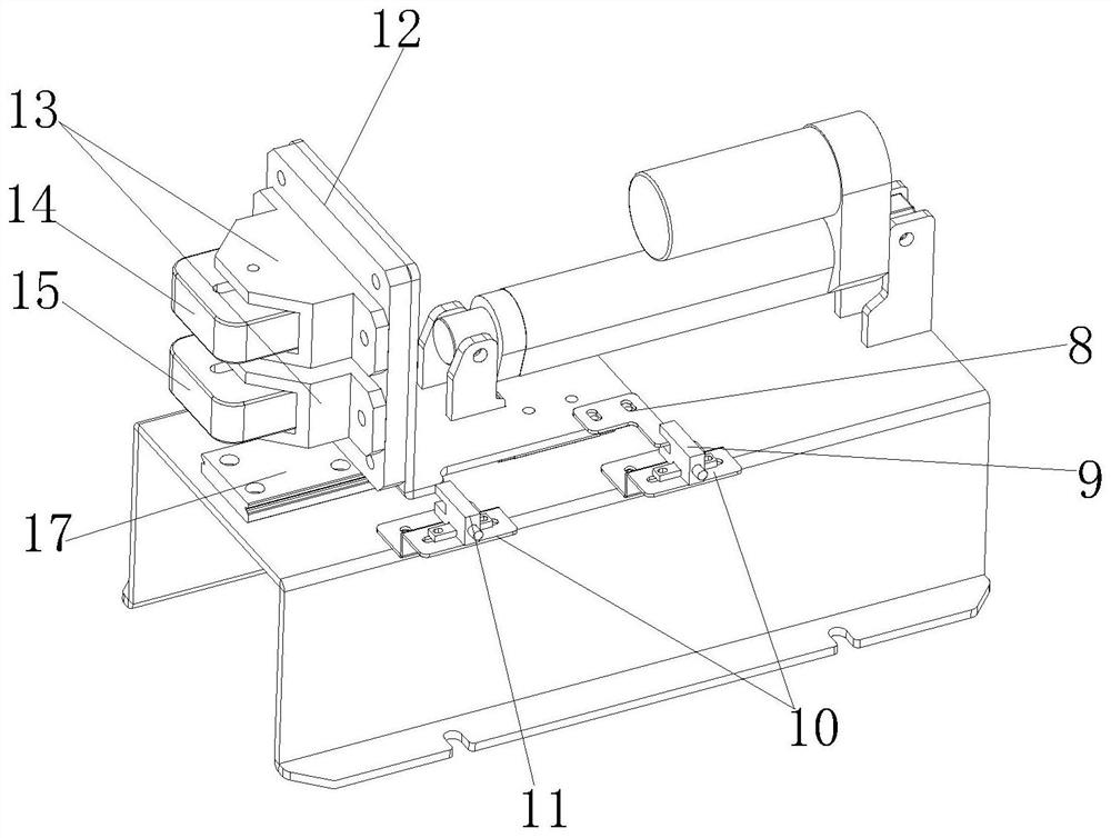
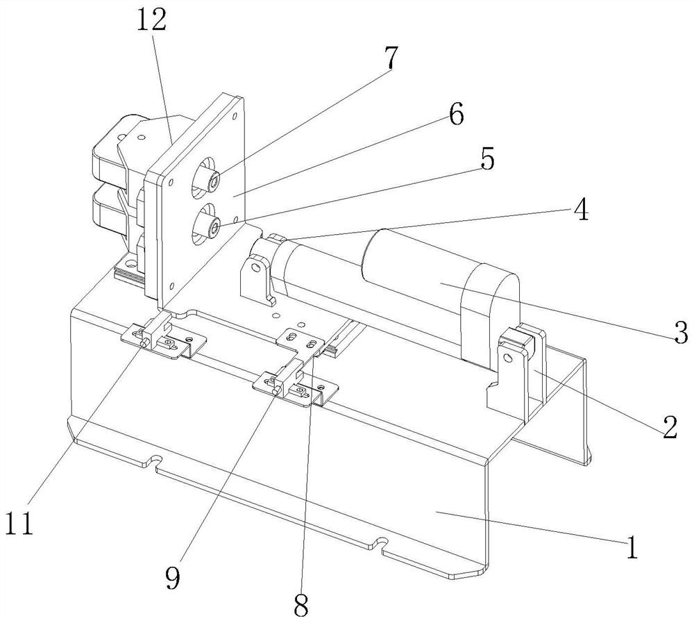
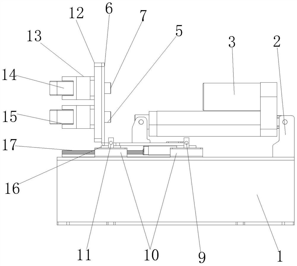
[0020] see Figure 1-3 , the present invention provides the following technical solutions: a mobile robot rapid automatic charging mechanism module, including a mounting bracket plate 1, the upper end of the mounting bracket plate 1 is provided with a telescopic bracket plate 6, and the lower end of the telescopic bracket plate 6 is provided with a linear slide Block 16, the position corresponding to the upper end of the mounting bracket plate 1 and the linear...


PUM


Abstract

The invention discloses a rapid automatic charging mechanism module for a mobile robot, and belongs to the technical field of mobile robots. The automatic charging mechanism module comprises a mounting support plate, a telescopic support plate is arranged at one end of the upper side of the mounting support plate, and a linear sliding block is arranged at the lower end of the telescopic support plate; and linear sliding rails are arranged at the positions, corresponding to the linear sliding blocks, of the upper end of the mounting support plate, a power source isolation plate is arranged on the side, away from the middle position of the mounting support plate, of the telescopic support plate, and a positive electrode contact block is arranged at the upper end of the other side of the power source isolation plate. An electric push rod is arranged, the power transmission mode of the electric push rod, the linear sliding block and the linear sliding rail is adopted, the design structure is reasonable and simple, production assembly and after-sales repair and maintenance are convenient, the ingenious power transmission structure design mode is adopted, rapid stretching or retracting of the rapid automatic charging mechanism can be achieved, and the automatic charging efficiency is improved.

Description

technical field [0001] The invention belongs to the technical field of mobile robots, and in particular relates to a fast automatic charging mechanism module of a mobile robot. Background technique [0002] The power transmission mode of the telescopic mechanism of the fast automatic charging mechanism module in the automatic charging pile used in the mobile robot industry is mostly screw drive or pneumatic cylinder drive. The time for the automatic charging mechanism to extend or retract is too long, which affects The efficiency of automatic charging, its complex structure, high requirements for processing accuracy, increased processing costs, inconvenient installation, and the unreasonable design of the limit sensor installation method, resulting in the detection of the limit stopper is not in place, so that the automatic charging mechanism cannot be effectively extended. out or retracted, the failure rate is high, resulting in unstable operation of the automatic charging ...

Claims


Application Information

Patent Timeline
Patent Type & Authority Applications(China)
IPC IPC(8): H02J7/00
CPCH02J7/0045Y02B40/00
Inventor 钟彦华
Owner 途灵机器人(东莞)有限公司
Why Eureka
Try Eureka