
Self-adaptive slope compensation circuit

A slope compensation and self-adaptive technology, which is applied in the direction of electrical components, adjusting electrical variables, instruments, etc., can solve the problems of sacrificing loop bandwidth and difficulty in loop compensation

Active Publication Date: 2021-05-14
UNIV OF ELECTRONICS SCI & TECH OF CHINA
View PDF10 Cites 7 Cited by
  • Summary
  • Abstract
  • Description
  • Claims
  • Application Information

AI Technical Summary

Problems solved by technology

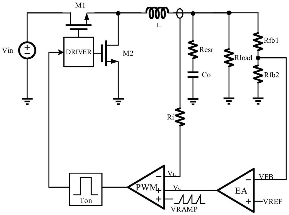
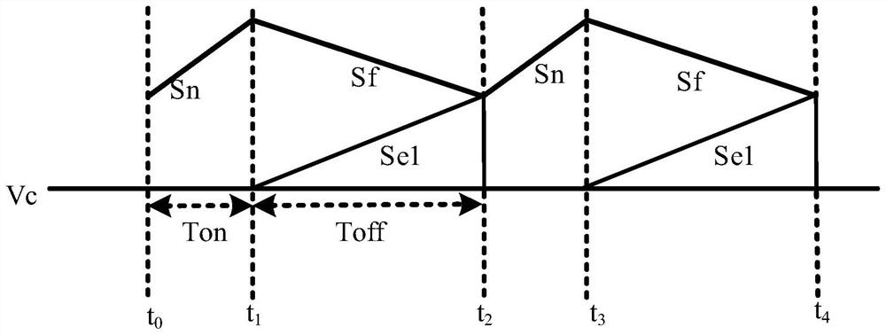
[0006] Compared with the traditional constant on-time control buck converter, the constant on-time control buck converter with fixed slope compensation will additionally introduce a fixed zero point and a moving pole due to the introduction of the slope. pole will make it more difficult to compensate the loop
Since the moving pole will change with the external working conditions, it is often designed to overcompensate to ensure the stability of the system in the worst case, and the result of this is to sacrifice the bandwidth of the loop

Method used


Image

  • Self-adaptive slope compensation circuit
  • Self-adaptive slope compensation circuit
  • Self-adaptive slope compensation circuit

Examples


Embodiment Construction

[0034] In order to make the object, technical solution and advantages of the present invention clearer, the present invention will be described in detail below in conjunction with the accompanying drawings. Apparently, the described embodiments are only some of the embodiments of the present invention, but not all of them. Based on the embodiments of the present invention, all other embodiments obtained by persons of ordinary skill in the art without making creative efforts belong to the protection scope of the present invention.

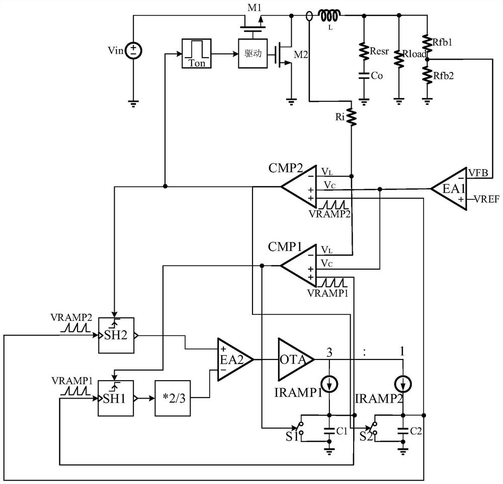
[0035] The adaptive slope compensation circuit proposed by the present invention is suitable for converters in current control mode. The converter changes the inductor current by controlling the on and off of the switch device, thereby controlling the output voltage. The adaptive slope compensation circuit of the present invention can sample The change of the inductor current generates a control signal for controlling the switching device in the con...


PUM


Abstract

The invention discloses a self-adaptive slope compensation circuit which is suitable for a converter in a current control mode, and realizes self-adaptive slope compensation by sampling and following an inductive current of the converter. A first slope voltage and a second slope voltage with fixed multiples are introduced, and the first slope voltage and the second slope voltage are sampled at two time points when an inductive current drops during an inductive current detection period. Then, the slope of the first slope voltage and the slope of the second slope voltage are regulated and controlled by measuring the size relation of the two sampling voltage values, and finally the relation between the slope of the first slope voltage and the slope of the second slope voltage and an inductive current declining slope can be fixed. In addition, a delay module is introduced into a control loop in the embodiment so that a control waveform can be achieved when there is no slope to be introduced, and introduction of an additional zero pole is avoided.

Description

technical field [0001] The invention belongs to the technical field of integrated circuits and power converters, and relates to an adaptive slope compensation circuit, which is suitable for converters in a current control mode. Background technique [0002] Current control mode converters include constant on-time controlled converters and adaptive on-time controlled converters, in which a constant on-time (Constant On-time, COT) controlled current mode DC-DC converter is used, Its core idea is to control the duty cycle and switching frequency by controlling the on-time constant and changing the valley current, so as to achieve the purpose of controlling the output voltage. The constant on-time control mode can also maintain stability when the duty cycle is greater than 50%, without generating sub-harmonic oscillations. Compared with the peak current mode, the slope compensation circuit module is saved, the circuit is simplified, and the stability is improved. [0003] For s...

Claims


Application Information

Patent Timeline
Patent Type & Authority Applications(China)
IPC IPC(8): H02M3/158
CPCH02M3/158
Inventor 甄少伟罗攀易子皓方舟吴东铭程雨凡张波
Owner UNIV OF ELECTRONICS SCI & TECH OF CHINA
Learn More