Supercharge Your Innovation With Domain-Expert AI Agents!

Low power solenoid with dropout detection and auto re-energization

An actuation and inductor technology, applied in the direction of electromagnet with armature, output power conversion device, DC power input conversion to DC power output, etc.

Active Publication Date: 2021-05-14
AUTOMATIC SWITCH CO
View PDF19 Cites 0 Cited by
  • Summary
  • Abstract
  • Description
  • Claims
  • Application Information

AI Technical Summary

Problems solved by technology

Therefore, if the solenoid were to experience mechanical punching or other event causing disengagement, the unit would remain in that state without any supervisory notice

Method used


Image

  • Low power solenoid with dropout detection and auto re-energization
  • Low power solenoid with dropout detection and auto re-energization
  • Low power solenoid with dropout detection and auto re-energization

Examples


Embodiment Construction

[0031] The above description of the drawings and the following written description of specific structures and functions are not intended to limit the scope of applicants' invention or the scope of the appended claims. Rather, the drawings and written description are provided to teach any person skilled in the art to make and use the invention for which patent protection is sought. Those skilled in the art will appreciate that not all features of the commercial embodiments of the present disclosure are described or shown for the sake of clarity and understanding. Those skilled in the art will also appreciate that the development of an actual commercial embodiment incorporating aspects of the present disclosure may require a number of implementation-specific decisions in order to achieve the developer's ultimate goals for the commercial embodiment. Such implementation-specific decisions may include, but may not be limited to, compliance with system-related, business-related, gov...


PUM


Abstract

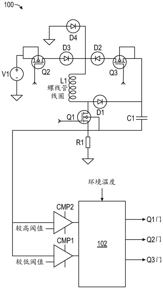
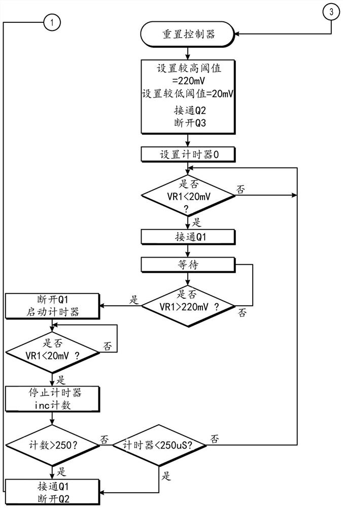
A solenoid control circuit (100) makes measurements during operation to determine the state of a solenoid (L1) and provides for rapid re-energization of a solenoid (L1) upon detection of a dropout condition. A method of controlling the solenoid (L1) includes closing an input switch (Q2), cycling a low side switch (Q1) based on voltage drop across a resistor (R1), opening the input switch (Q2) after a time interval, closing the low side switch (Q1) and driving a discharge switch (Q3) to control the discharge current rate from an energy storage device (C1) to the solenoid (L1). The method can include determining a condition of the solenoid (L1) based on a time interval between actuation of comparators (CMP1, CMP2) and maintaining a level of energy in the energy storage device (C1) sufficient to cause the solenoid to produce a magnetic field for actuating a valve.

Description

[0001] Cross References to Related Applications [0002] This application is a PCT of U.S. Patent Application 16 / 103,602 filed August 14, 2018, the entire contents of which are hereby incorporated by reference. [0003] Statement Regarding Federally Sponsored Research or Development [0004] Not applicable [0005] Refer to the appendix [0006] Not applicable [0007] Background of the invention [0008] The invention disclosed and taught herein relates generally to control systems, and more particularly to low power control systems. [0009] Related Background Note [0010] U.S. Patent No. 5,532,526 teaches "a control circuit for supplying a current to a load with a high-amplitude portion and a low-amplitude portion, wherein the high-amplitude portion has a fast rising edge. The circuit input is connected to a low-voltage power supply and includes A plurality of actuator circuits connected in parallel between the input terminals, and each actuator circuit includes a capa...

Claims


Application Information

Patent Timeline
Patent Type & Authority Applications(China)
IPC IPC(8): H01F7/18H02M3/155H01H47/04
CPCH01F7/1816H01F2007/1822H01H47/043H02M3/1555H02M3/155
Inventor J.哈勒
Owner AUTOMATIC SWITCH CO
Features
  • R&D
  • Intellectual Property
  • Life Sciences
  • Materials
  • Tech Scout
  • Unparalleled Data Quality
  • Higher Quality Content
  • 60% Fewer Hallucinations
Learn More