
Welding gun protection device and welding equipment

A technology for protective devices and welding equipment, which is applied in welding equipment, welding protection devices, arc welding equipment, etc., and can solve problems such as inability to protect the torch head

Pending Publication Date: 2021-05-18
DALIAN ZHIHUIDA TECH CO LTD
View PDF0 Cites 0 Cited by
  • Summary
  • Abstract
  • Description
  • Claims
  • Application Information

AI Technical Summary

Problems solved by technology

[0003] The existing protective structure can only be applied to the situation where the gun head collides directly in front of it, but in actual operation, the position where the gun head collides is multi-directional, and the existing protective structure cannot realize all-round protection for the gun head

Method used


Image

  • Welding gun protection device and welding equipment
  • Welding gun protection device and welding equipment
  • Welding gun protection device and welding equipment

Examples


Embodiment 1

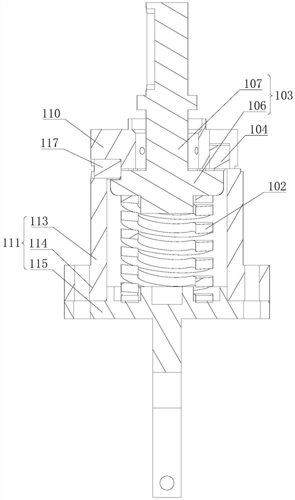
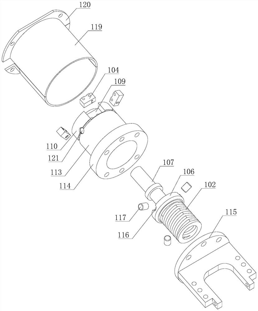
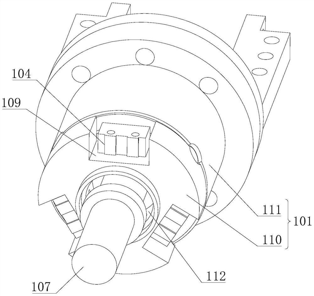
[0045] see Figure 1 to Figure 4 As shown, the welding torch protection device provided by the present application is used for welding equipment. The welding torch protection device includes a housing 101, an elastic member 102, a trigger 103 and a plurality of trigger switches 104; one end of the housing 101 is connected to a welding torch 105; the trigger 103 Including the abutment part 106 and the connection part 107, the abutment part 106 is located in the housing 101, the connection part 107 passes through the other end of the housing 101, and is connected with the body of the welding equipment, specifically, Figure 4 A partial structure 108 of the body of the welding device is shown in .

[0046] A plurality of trigger switches 104 are mounted on the housing 101 and arranged at intervals in the circumferential direction of the contact portion 106. Each trigger switch 104 is connected with an alarm device and a protection program of the welding equipment. Corresponds to...

Embodiment 2

[0061] The welding torch protection device in the second embodiment is an improvement on the basis of the above embodiment. The technical content disclosed in the above embodiment will not be described repeatedly, and the content disclosed in the above embodiment also belongs to the content disclosed in the second embodiment.

[0062] In the optional solution of this embodiment, the abutment portion 106 is provided with a limit gap, and the housing 101 is formed with a limit pin 117 inserted into the limit gap; when the end of the limit gap away from the elastic member 102 is the first closed end When the limit pin 117 forms a gap with the first closed end; when the end of the limit gap close to the elastic member 102 is the second closed end, the limit pin 117 forms a gap with the second closed end.

[0063] In this example, see Figure 5 to Figure 7 As shown, the limit gap can have various structural forms, and is not limited to figure 2 with Figure 5 The groove structur...

Embodiment 3

[0072] Embodiment 3 of the present application provides a welding device, which includes the welding torch protection device of any one of the above embodiments, and thus has all the beneficial technical effects of the welding torch protection device of any one of the above embodiments, which will not be repeated here.


PUM


Abstract

The invention relates to the technical field of welding equipment, in particular to a welding gun protection device and welding equipment. The welding gun protection device comprises a shell, an elastic part, a trigger part and a plurality of trigger switches. The shell is connected with a welding gun; the triggering part comprises an abutting part and a connecting part, the abutting part is located in the shell, and the connecting part penetrates out of the shell; the trigger switches are installed on the shell and arranged in the circumferential direction of the abutting part at intervals; one end of the elastic part is connected with the shell, the other end of the elastic part abuts against the abutting part so that the abutting part can abut against the trigger switches, the elastic part can deform in any direction so as to drive the shell to swing relative to the trigger part, and therefore the at least one trigger switch can be far away from the abutting part. When a gun head is collided, the elastic part deforms to drive the shell to move relative to the trigger part, the attaching state between the trigger part and the trigger switches in different directions is changed, and protection programs of an alarm device and the welding equipment can be triggered in all directions, so that multi-direction protection on the gun head is achieved.

Description

technical field [0001] The present application relates to the technical field of welding equipment, in particular to a welding torch protection device and welding equipment. Background technique [0002] During the automatic welding process of the torch head of the argon arc welding torch, the torch head will contact and collide with the welding workpiece. In order to avoid damage to the torch head, a protective structure is mostly installed at the rear of the torch head in the prior art. [0003] The existing protective structure can only be applied to the situation where the gun head collides directly in front of it, but in actual operation, the position where the gun head collides is multi-directional, and the existing protective structure cannot realize all-round protection for the gun head . Contents of the invention [0004] The purpose of the present application is to provide a welding torch protection device and welding equipment, which can trigger the alarm devic...

Claims


Application Information

Patent Timeline
IPC IPC(8): B23K9/32B23K9/16
CPCB23K9/16B23K9/321
Inventor 林泉王增武刘克欣
Owner DALIAN ZHIHUIDA TECH CO LTD
Learn More