A program-controlled load adaptive variable voltage constant current source module

A constant current source module, self-adaptive technology, applied in the direction of adjusting electrical variables, control/regulating systems, instruments, etc., can solve problems such as output current exceeding the limit current, load or instrument damage, etc.

Inactive Publication Date: 2020-10-20
长春昌鼎电子科技有限责任公司
View PDF1 Cites 0 Cited by
  • Summary
  • Abstract
  • Description
  • Claims
  • Application Information

AI Technical Summary

Problems solved by technology

In addition, the technical solution disclosed in the above-mentioned patent does not have an over-current power-off protection function. Once the current-limiting module fails, it will cause the risk that the output current will exceed the limited current (generally the maximum safe current), resulting in damage to the load or the instrument.

Method used


Image

  • A program-controlled load adaptive variable voltage constant current source module
  • A program-controlled load adaptive variable voltage constant current source module
  • A program-controlled load adaptive variable voltage constant current source module

Examples


Embodiment 1

[0033] Embodiment 1 Overall structure of the present invention

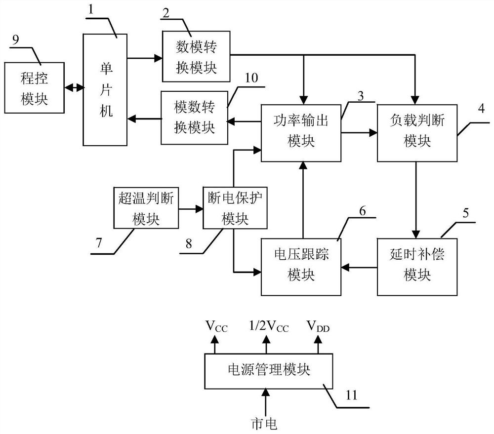
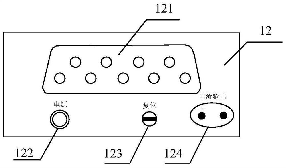
[0034] Overall structure of the present invention is as figure 1 As shown, there are single-chip microcomputer 1, digital-to-analog conversion module 2, power output module 3, load judgment module 4, delay compensation module 5, voltage tracking module 6, power-off protection module 8, over-temperature judgment module 7, program control module 9, Analog-to-digital conversion module 10, power management module 11 and front panel 12; wherein, single-chip microcomputer 1 is connected with program control module 9, analog-to-digital conversion module 10, digital-to-analog conversion module 2 respectively, and digital-to-analog conversion module 2 is connected with power output module 3, load The judging module 4 is connected, the power output module 3 is connected with the analog-to-digital conversion module 10 and the load judging module 4 respectively, the load judging module 4 is connected with the delay compensat...

Embodiment 2

[0035] Embodiment 2 The power output module of the present invention

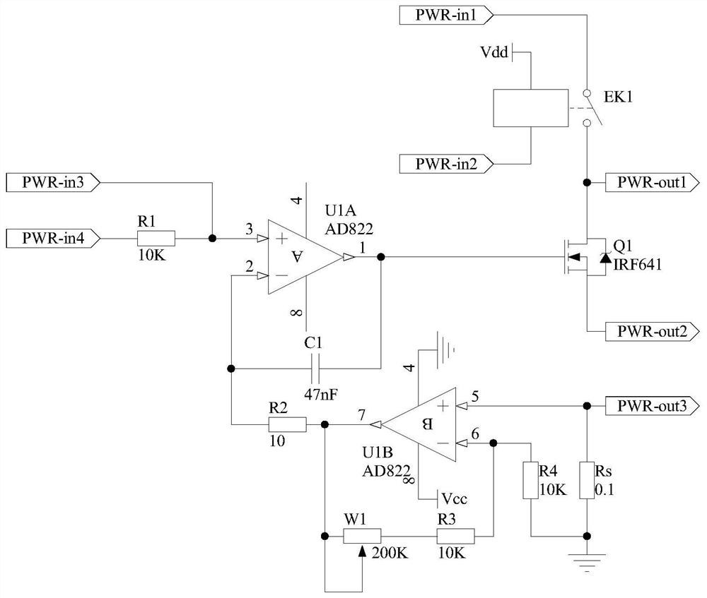
[0036] The schematic circuit diagram of the power output module 3 is as follows image 3 As shown, one end of the switch of the relay EK1 is used as the first input end of the power output module 3, which is marked as port PWR-in1, and the other end is connected to the drain of the field effect transistor Q1, and is used as the first output end of the power output module 3 terminal, denoted as port PWR-out1, one end of the coil of relay EK1 is connected to the power supply Vdd, and the other end is used as the second input terminal of power output module 3, denoted as port PWR-in2, the gate of FET Q1 is connected to the operational amplifier The output terminal of U1A is connected, and the source is used as the second output terminal of the power output module 3, which is recorded as port PWR-out2. The input end is marked as port PWR-in3, and the other end of resistor R1 is used as the fourth input end of ...

Embodiment 3

[0038] Embodiment 3 The load judging module of the present invention

[0039] The principle circuit of the load judging module 4 is as Figure 4 As shown, the non-inverting input terminal of the operational amplifier U2A is used as the first input terminal of the load judgment module 4, which is denoted as port Vjdg-in1, and is connected to the port PWR-out1 of the power output module 3, and the inverting input terminal of the operational amplifier U2A is connected to the The output terminal of operational amplifier U2A is connected to one end of resistor R5, the other end of resistor R5 is connected to one end of resistor R6 and the same-inverting input terminal of operational amplifier U3A, the other end of resistor R6 is grounded, and the output terminal of operational amplifier U3A is connected to the in-phase input terminal of operational amplifier U3A. One end is connected to one end of the resistor R9, the other end of the resistor R8 is connected to the inverting input...


PUM


Abstract

The invention discloses a program control type load adaptive variable voltage constant current source module, and belongs to the technical field of electronic equipment. The module comprises main structures including a single-chip microcomputer (1), a digital-to-analog conversion module (2), a power output module (3), a load judgment module (4), a delay compensation module (5), a voltage trackingmodule (6), a power-off protection module (8), a program control module (9), and the like. The module can actively adapt to the change of a load during working, and has the advantages of high efficiency, wide load adaptation range, high safety, high reliability and the like.

Description

technical field [0001] The invention belongs to the technical field of electronic equipment. It particularly relates to a program-controlled load adaptive variable voltage constant current source module. Background technique [0002] Constant current sources have important applications in many fields such as LED drive, laser drive, sensor drive, and various glow discharge light source drives. The basic principle of the constant current source circuit is generally to use the nonlinear characteristics of the triode or FET and the deep negative feedback technology to make the output current controlled by the control voltage, and keep the current flowing through the load constant when the load changes. In the constant current source circuit, the stability of the current and the efficiency of the circuit are two crucial parameters. [0003] The existing technology closest to the present invention is the Chinese patent "A double-loop feedback constant current source circuit" (ap...

Claims


Application Information

Patent Timeline
Patent Type & Authority Patents(China)
IPC IPC(8): G05F1/565
CPCG05F1/565
Inventor 田小建梁雪邓军刘大凯高鹏彪李尚马春阳由家旭
Owner 长春昌鼎电子科技有限责任公司
Why Eureka
Try Eureka