
Solid-liquid two-phase separation type anaerobic digestion equipment

An anaerobic digestion and phase separation technology, applied in biological sludge treatment, dehydration/drying/thickened sludge treatment, etc., can solve problems such as long-term separation

Inactive Publication Date: 2021-05-18
陈锦
View PDF0 Cites 0 Cited by
  • Summary
  • Abstract
  • Description
  • Claims
  • Application Information

AI Technical Summary

Problems solved by technology

[0003] Based on the inventors' findings above, the existing solid-liquid two-phase separation type anaerobic digestion equipment mainly has the following disadvantages, such as: because a certain amount of water is mixed in the fermented feces, it is necessary to remove the moisture in the feces Separation can be used as fertilizer, and when separating the water mixed in the feces, the water drips down through its own gravity to achieve the effect of solid-liquid separation, and the water drips down through the gravity of the water itself, It takes a long time to separate the water placed on the surface of the feces

Method used


Image

  • Solid-liquid two-phase separation type anaerobic digestion equipment
  • Solid-liquid two-phase separation type anaerobic digestion equipment
  • Solid-liquid two-phase separation type anaerobic digestion equipment

Examples


Embodiment 1

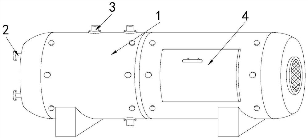
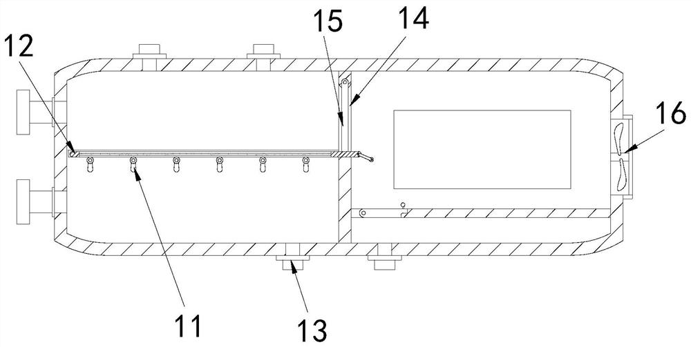
[0024] Example 1: Please refer to Figure 1-Figure 4 , the specific embodiments of the present invention are as follows:

[0025] Its structure includes a main body 1, a feed port 2, an exhaust port 3, and a box door 4. The side end of the main body 1 is provided with a feed port 2, and there are two exhaust ports 3, which are respectively located on the main body 1. The two ends of the top of the box door 4 are provided with two, and they are engaged with the front and rear ends of the main body 1 respectively. The main body 1 includes a sliding block 11, a filter device 12, a sewage outlet 13, a partition 14, plate 15, hot air blower 16, the sliding block 11 is provided with more than five, and is installed laterally at both ends inside the main body 1, the filter device 12 is installed laterally on the upper end surface of the sliding block 11, and the sewage outlet 13 is set At the bottom of the sewage outlet 13 , the partition 14 is located in the middle of the main body...

Embodiment 2

[0029] Example 2: Please refer to Figure 5-Figure 7 , the specific embodiments of the present invention are as follows:

[0030] The partition plate 15 includes an engaging shaft b1, a slot b2, a mounting groove b3, a tension spring b4, a lower top block b5, and a sealing layer b6. The engaging shaft b1 is arranged on the top of the partition plate 15, so that The cutout b2 is located at the rear end of the partition plate 15, the installation groove b3 is located at the inner bottom of the partition board 15, the tension spring b4 is installed inside the installation groove b3, and the lower top block b5 is clamped fit in the installation groove b3, the sealing layer b6 is attached to the front end surface of the partition plate 15, and the tension spring b4 is movably matched with the lower top block b5, which is beneficial to pull the partition plate 15 when closing The extension spring b4 resets and drives the lower top block b5 to move downward, so that the sealing laye...


PUM


Abstract

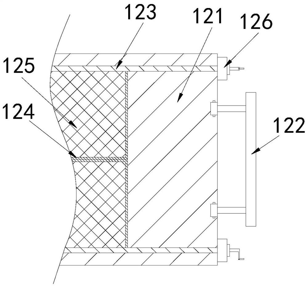
The invention discloses solid-liquid two-phase separation type anaerobic digestion equipment, which structurally comprises a main body, feed ports, exhaust ports and two box doors, wherein the feed ports are formed in the side end of the main body, the two exhaust ports are located at the two ends of the top of the main body respectively, and the two box doors are clamped to the front end and the rear end of the main body respectively. The main body comprises a sliding block, a filtering device, a sewage draining exit, a partition plate, a partition plate and an air heater, the filtering device comprises a supporting plate, a handle, a rotating column, a supporting frame, a filtering plate and a clamping device, and the clamping device comprises a rotating handle, a clamping hole, a movable groove, a reset spring and a pull rod. The filter device is dragged to the other end of the interior of the main body, and then the clamping device drives the rotating column to rotate, so that the excrement on the filter plate can fall into the main body; the excrement is dried through the air heater, so that water in the excrement can be quickly separated.

Description

technical field [0001] The invention relates to the field of ventilated solid-phase fermentation equipment, in particular to a solid-liquid two-phase separation type anaerobic digestion equipment. Background technique [0002] The feces in pastures in agricultural production contain a large amount of organic matter. Anaerobic digestion equipment can be used to ferment solid organic matter. The biogas produced by fermentation can be recycled and used. After fermentation, the water mixed in feces needs to be separated. Manure can be used as fertilizer. [0003] Based on the inventors' findings above, the existing solid-liquid two-phase separation type anaerobic digestion equipment mainly has the following disadvantages, such as: because a certain amount of water is mixed in the fermented feces, it is necessary to remove the moisture in the feces Separation can be used as fertilizer, and when separating the water mixed in the feces, the water drips down through its own gravity...

Claims


Application Information

Patent Timeline
IPC IPC(8): C02F11/04C02F11/12C02F11/13
CPCC02F11/04C02F11/12C02F11/13
Inventor 陈锦
Owner 陈锦
Learn More