
Uniform heating type annealing furnace for glass bottle production

A technology of uniform heating and glass bottles, applied in the field of glass bottle production, can solve the problems of affecting product quality, low product qualification rate, and high production cost

Active Publication Date: 2021-05-18
涿鹿亿达玻璃容器有限公司
View PDF4 Cites 4 Cited by
  • Summary
  • Abstract
  • Description
  • Claims
  • Application Information

AI Technical Summary

Problems solved by technology

[0003]The existing uniform heating type annealing furnace for glass bottle production is difficult to achieve uniform heating of glass bottles, which in turn affects product quality and leads to low product qualification rate , the production cost increases, and there are certain deficiencies

Method used


Image

  • Uniform heating type annealing furnace for glass bottle production
  • Uniform heating type annealing furnace for glass bottle production
  • Uniform heating type annealing furnace for glass bottle production

Examples


Embodiment 1

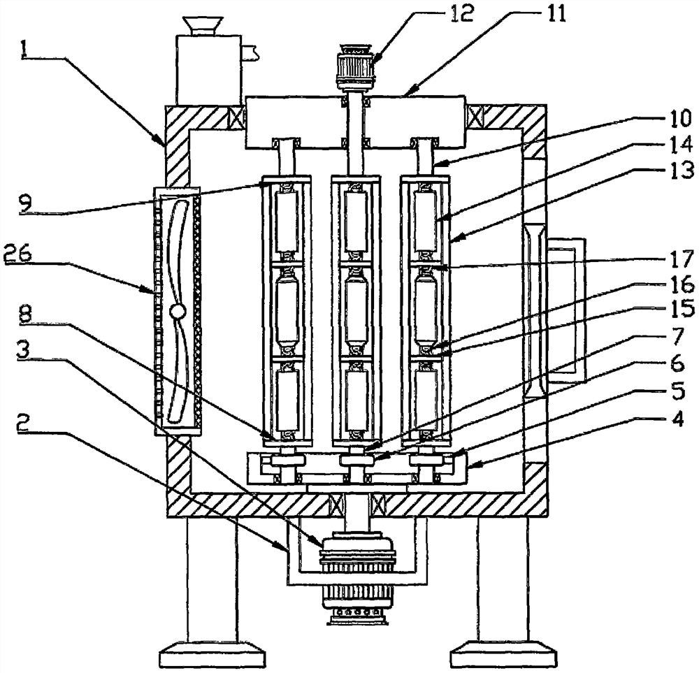
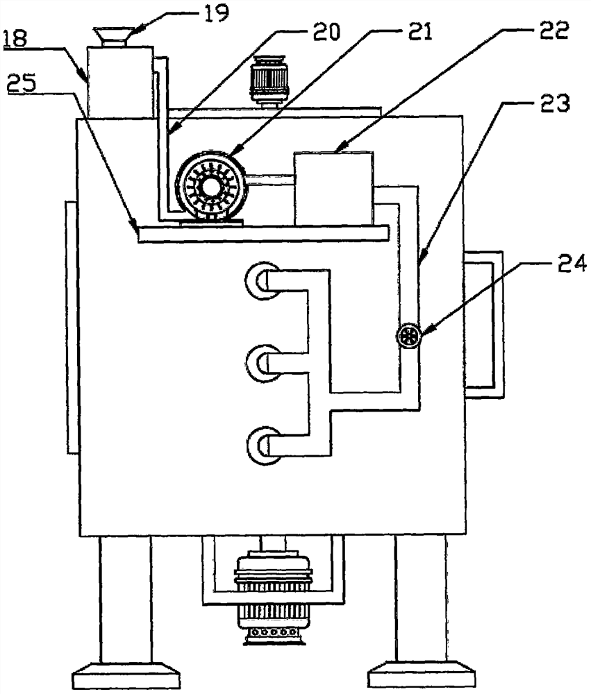
[0025] see Figure 1-4 , a uniformly heated annealing furnace for the production of glass bottles, comprising a furnace body 1, the furnace body 1 is a cuboid structure, the inside of the furnace body 1 is provided with a furnace cavity, and the center of the bottom surface of the furnace body 1 is fixedly connected with a motor Frame 2, the first motor 3 is fixedly installed on the motor frame 2, the output shaft of the first motor 3 runs through the bottom plate of the furnace body 1 and the bottom of the extended furnace cavity is fixedly connected to the center of the bottom surface of the large turntable 4, and the top of the large turntable 4 A cylindrical groove is opened on the surface, and the groove wall of the cylindrical groove is rotatably connected to the outer surface of the inner gear ring 5, and the inner gear ring 5 is meshed with several spur gears 6, and the spur gears 6 are fixedly sleeved on the first rotating shaft 7 outer surface, the bottom end of the ...

Embodiment 2

[0034] This embodiment is a further improvement made on the basis of Embodiment 1, specifically as follows:

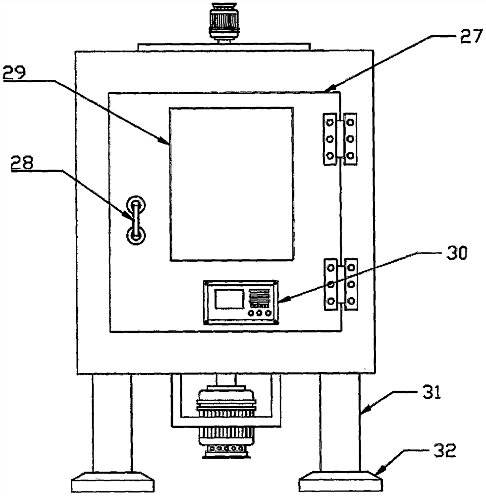
[0035] see Figure 1-4, the front end of the furnace body 1 is open, and a door 27 is installed at the opening through a hinge, and a handle 28 and a viewing window 29 are installed on the door 27; a controller 30 is also fixedly installed on the door 27, The controller 30 is electrically connected to the first motor 3, the second motor 12, the fan 21, the heater 22 and the radiator 26, and the door 27 is conveniently opened by setting the handle 28, and the viewing window 29 is set to facilitate observation of the furnace cavity The heating and cooling conditions of the inner glass bottle are practical.


PUM


Abstract

The invention discloses a uniform heating type annealing furnace for glass bottle production. The furnace comprises a furnace body; a first motor is fixedly installed on the bottom face of the furnace body; an output shaft of the first motor penetrates through a bottom plate of the furnace body and is fixedly connected to a large rotating disc; an inner gear ring is rotationally connected into a cylindrical groove in the top face of the large rotating disc; the inner gear ring is connected with a plurality of straight gears in a meshed mode; the straight gears fixedly sleeve the outer surfaces of first rotating shafts; the top ends of the first rotating shafts are fixedly connected with first small rotating discs; second small rotating discs are arranged over the first small rotating discs at intervals; glass bottle fixing mechanisms are arranged between the first small rotating discs and the second small rotating discs; second rotating shafts are fixedly connected to the sides, away from the first small rotating discs, of the second small rotating discs; the second rotating shafts are rotationally connected with rotating wheels through bearings; any second rotating shaft penetrates through the rotating wheels and is fixedly connected to a second motor; the first motor drives a whole glass bottle to rotate, and the second motor drives the glass bottle to revolve around its own axis, so that uniform heating is achieved, and product quality is guaranteed.

Description

technical field [0001] The invention relates to the technical field of glass bottle production, in particular to a uniformly heated annealing furnace for glass bottle production. Background technique [0002] Annealing is a metal heat treatment process, which refers to slowly heating the metal to a certain temperature, keeping it for a sufficient time, and then cooling it at an appropriate speed. The purpose is to reduce hardness, improve machinability; reduce residual stress, stabilize size, reduce deformation and crack tendency; refine grain, adjust structure, and eliminate structure defects. To be precise, annealing is a heat treatment process for materials, including metal materials and non-metal materials. Moreover, the purpose of annealing new materials is similar to that of traditional metal annealing. [0003] The existing uniform heating type annealing furnace for the production of glass bottles is difficult to achieve uniform heating of glass bottles, thereby aff...

Claims


Application Information

Patent Timeline
IPC IPC(8): C03B25/00
CPCC03B25/00Y02P40/57
Inventor 孙贵富
Owner 涿鹿亿达玻璃容器有限公司
Learn More