
A cooling device for an automobile engine

A technology of automobile engine and heat dissipation device, which is applied in the direction of engine cooling, engine components, machine/engine, etc., can solve problems such as reducing fan efficiency, and achieve the effect of improving installation efficiency, improving convenience, and improving efficiency.

Active Publication Date: 2022-03-11
DONGFENG LIUZHOU MOTOR
View PDF24 Cites 0 Cited by
  • Summary
  • Abstract
  • Description
  • Claims
  • Application Information

AI Technical Summary

Problems solved by technology

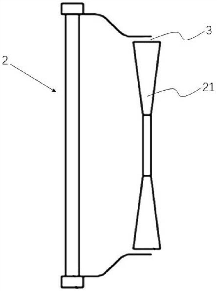
[0003] At present, the most widely used in the market are such as figure 1 In the open windshield 2 shown, the fan 21 is a high-speed rotating part. In order to prevent structural damage caused by dynamic interference during the movement, a certain gap 3 must be maintained between the fan 21 and the open windshield 2. For the open The air cover 2 and the fan 21, the blade tip clearance of the fan 21 will produce obvious secondary circulation, thereby reducing the efficiency of the fan

Method used


Image

  • A cooling device for an automobile engine
  • A cooling device for an automobile engine
  • A cooling device for an automobile engine

Examples


Embodiment Construction

[0024] The specific implementation manners of the present invention will be further described in detail below in conjunction with the accompanying drawings and embodiments. The following examples are used to illustrate the present invention, but are not intended to limit the scope of the present invention.

[0025] In describing the present invention, it should be understood that the terms "upper", "lower", "front", "rear", "left", "right", "vertical", "horizontal", The orientations or positional relationships indicated by "top", "bottom", "inner", "outer", etc. are based on the orientations or positional relationships shown in the drawings, and are only for the convenience of describing the present invention and simplifying the description, rather than indicating or implying the It should not be construed as limiting the invention that a device or element must have a particular orientation, be constructed, and operate in a particular orientation. In the present invention, "i...


PUM


Abstract

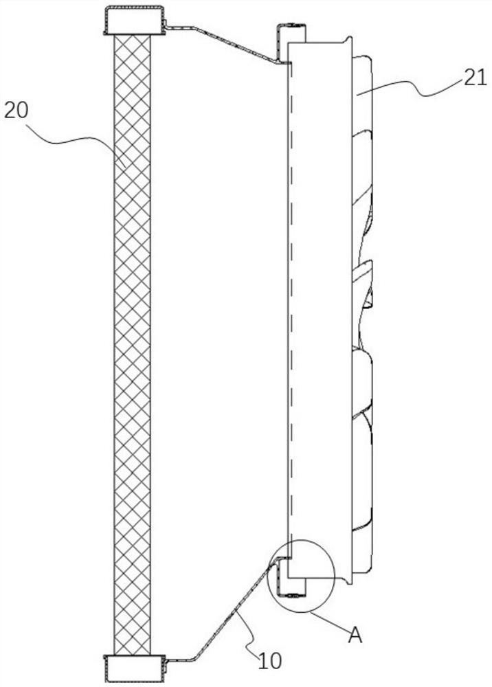
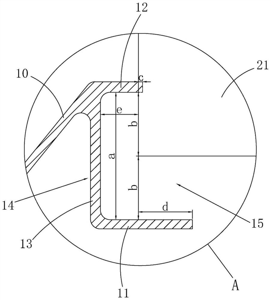
The invention relates to the technical field of engine radiators for mobile machinery, and discloses a heat dissipation device for an automobile engine of the present invention, which includes a windshield and a fan, the windshield and the fan are coaxially installed, the windshield includes a U-shaped ring, The type ring includes a flexible outer ring, a flexible inner ring and a connecting ring. The connecting ring is connected to the inner end of the flexible outer ring and defines an accommodation groove with the flexible outer ring. One end of the fan is accommodated in the accommodation groove, and the connecting ring is away from the flexible outer ring. One end protrudes toward the fan direction to form a flexible inner ring, a gap is defined between the outer peripheral wall of the fan and the flexible outer ring, and the materials of the flexible inner ring and the flexible outer ring are flexible materials. The heat dissipation device of the automobile engine of the present invention enables smooth assembly of the U-shaped windshield and convenient after-sales treatment, eliminates secondary circulation and improves fan efficiency at the same time.

Description

technical field [0001] The invention relates to the technical field of radiators for mobile machinery engines, in particular to a radiator for automobile engines. Background technique [0002] The windshield acts as a connecting channel that transitions from the square radiator to the circularly moving axial flow cooling fan, which can effectively improve fan efficiency, make the airflow through the radiator core evenly distributed, and reduce the backflow of hot air in the engine compartment. [0003] At present, the most widely used in the market are such as figure 1 In the open windshield 2 shown, the fan 21 is a high-speed rotating part. In order to prevent structural damage caused by dynamic interference during the movement, a certain gap 3 must be maintained between the fan 21 and the open windshield 2. For the open The air cover 2 and the fan 21, the tip clearance of the fan 21 will produce obvious secondary circulation, thereby reducing the efficiency of the fan. ...

Claims


Application Information

Patent Timeline
Patent Type & Authority Patents(China)
IPC IPC(8): F01P5/02F01P5/06F04D29/64F04D29/02
CPCF01P5/02F01P5/06F04D29/646F04D29/023
Inventor 陆增俊栗广生冯哲陈锦赖凡李程肖飞唐荣江
Owner DONGFENG LIUZHOU MOTOR
Learn More