Humidifier for laboratory equipment

A technology for laboratory equipment and humidifiers, applied in air humidification systems, lighting and heating equipment, applications, etc., can solve the problems of low humidification effect, occupying space, and poor adaptability.

Active Publication Date: 2021-05-18
HEBEI CHEM & PHARMA COLLEGE
View PDF10 Cites 3 Cited by
  • Summary
  • Abstract
  • Description
  • Claims
  • Application Information

AI Technical Summary

Problems solved by technology

[0002] Existing humidifiers for laboratory equipment have a single structure, a single humidification direction, uneven distribution of humidity, poor humidificati

Method used


Image

  • Humidifier for laboratory equipment
  • Humidifier for laboratory equipment
  • Humidifier for laboratory equipment

Examples


Embodiment Construction

[0024] The present invention will be further described below in conjunction with the accompanying drawings.

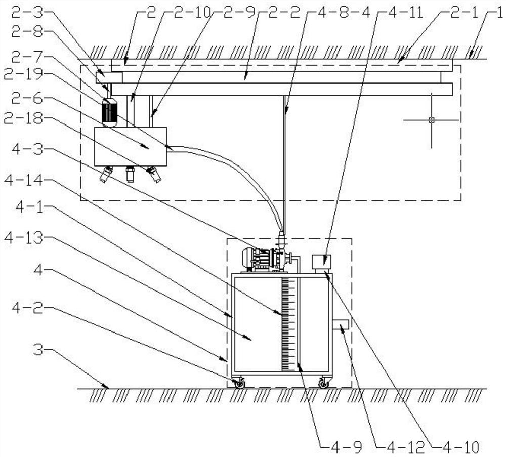
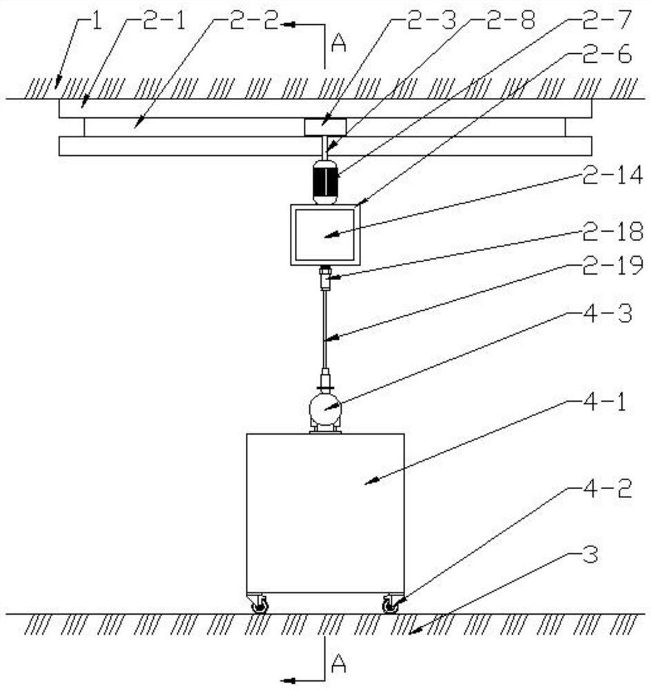
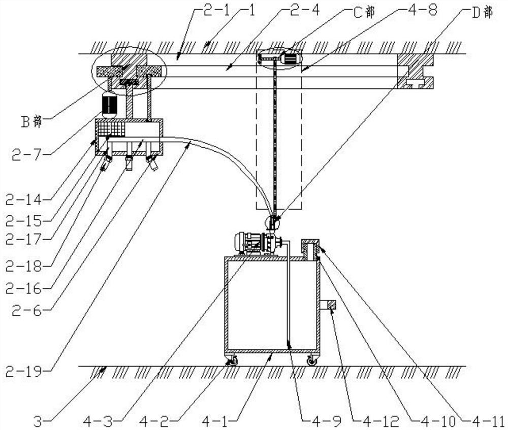
[0025] see as Figure 1 to Figure 6 As shown, the technical scheme adopted in this specific embodiment is: it includes that it includes a spraying mechanism 2 and a moving mechanism 4; the ceiling 1 is provided with a spraying mechanism 2; Roller 2-3, No. 2 roller 2-5, box body 2-6, No. 1 motor 2-7, No. 1 rotating shaft 2-8, No. 2 rotating shaft 2-9, connecting rod 2-10, No. 3 roller 2- 12. Door body 2-14, battery 2-15, No. 1 water pipe 2-16, No. 2 water pipe 2-17, atomizing nozzle 2-18 and corrugated pipe 2-19; ​​ceiling 1 is fixed with a circular track 2- 1; No. 1 chute 2-2 is provided on the outer ring wall of the circular track 2-1, and a No. 1 roller 2-3 is provided for rolling in the No. 1 chute 2-2; the inner ring wall of the circular track 2-1 is provided with No. 2 chute 2-4, No. 2 chute 2-4 rolls and is provided with No. 2 roller 2-5; The bottom of ring tra...


PUM


Abstract

The invention discloses a humidifier for laboratory equipment, and relates to the technical field of humidifying equipment. An annular rail is fixed to a ceiling board, a first sliding groove is formed in the outer ring wall of the annular rail, and a first rolling wheel is arranged in the first sliding groove in a rolling mode; a second sliding groove is formed in the inner ring wall of the annular rail, and a second rolling wheel is arranged in the second sliding groove in a rolling mode; a box body is arranged below the annular rail; a first motor is fixed to the outer side of a top plate of the box body; a first rotating shaft is fixed to an output shaft of the first motor, and the top end of the first rotating shaft is fixed to the middle of the bottom of the first rolling wheel; and the inner side of the top plate of the box body is connected with a second rotating shaft through a bearing in a screwing mode, and the top end of the second rotating shaft is connected with the middle of the bottom of a second rolling wheel through a bearing in a screwing mode. A laboratory can be fully, uniformly and quickly humidified, the use of a water tank and the delivery of water are not influenced, and the practicability is improved; and the humidifier can be moved away in time after humidification is completed, the space of the laboratory is not occupied, and use of the laboratory is not affected.

Description

technical field [0001] The invention relates to the technical field of humidification equipment, in particular to a humidifier for laboratory equipment. Background technique [0002] Existing humidifiers for laboratory equipment have a single structure, a single humidification direction, uneven distribution of humidity, poor humidification performance, low humidification effect, and will take up space when not in use, and the adaptability is not wide. A humidifier for laboratory equipment is proposed. Contents of the invention [0003] The object of the present invention is to address the defects and deficiencies of the prior art, and propose a humidifier for laboratory equipment, so that the laboratory can be fully, uniformly and quickly humidified, without affecting the use of the water tank and the transfer of water, and improving the practicability; It can be removed in time after the humidification is completed, does not occupy the space of the laboratory, and does n...

Claims


Application Information

Patent Timeline
IPC IPC(8): F24F6/14F24F13/00F24F13/32
CPCF24F6/14F24F13/00F24F13/32F24F2006/146F24F2221/125
Inventor 姜伟星
Owner HEBEI CHEM & PHARMA COLLEGE
Why Eureka
Try Eureka