
Indoor humidity and temperature control system

A technology for regulating system and humidity, which is applied in air-conditioning systems, space heating and ventilation details, and household heating, etc. It can solve the problems of increasing air flow resistance, reducing air-conditioning effect, and destroying the aerodynamic shape of wind turbines. The effect of reducing drag

Inactive Publication Date: 2017-11-07
UNIV OF JINAN
View PDF8 Cites 0 Cited by
  • Summary
  • Abstract
  • Description
  • Claims
  • Application Information

AI Technical Summary

Problems solved by technology

[0004] The CN201421141Y patent is characterized in that "a humidifying device is provided on the inside of the air inlet and on the front side of the fan part. Under the action of the fan part, the external air enters the interior of the electrical appliance from the air inlet, passes through the humidifying device, the exhaust duct, and then is discharged from the air outlet" because The humidifying device is on the side of the air inlet. When the air conditioner is used for heating, the humidification is good. But when the air conditioner is used for cooling, the humidifier device is at the air inlet, so the moisture will be discharged through the indoor heat exchanger (that is, the evaporator). Then the moisture will frost on the indoor heat exchanger (evaporator), not only the humidification effect will be greatly reduced, but also the heat transfer effect of the indoor heat exchanger will be greatly reduced after frosting, resulting in insufficient cooling capacity of the air conditioner.
[0005] "CN103438505A humidifying device, air-conditioning indoor unit, air-conditioning and air-conditioning humidification method" is characterized by "the brushes installed on the blades of the air flow wheel," which destroys the aerodynamic shape of the air flow wheel, and increases the air flow resistance, thus reducing the air conditioning effect

Method used


Image

  • Indoor humidity and temperature control system
  • Indoor humidity and temperature control system
  • Indoor humidity and temperature control system

Examples


Embodiment 1

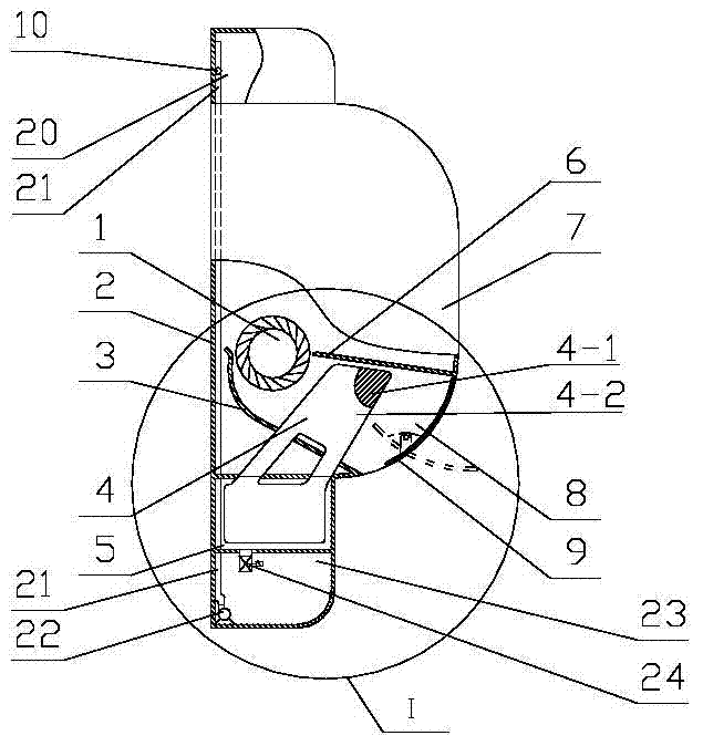
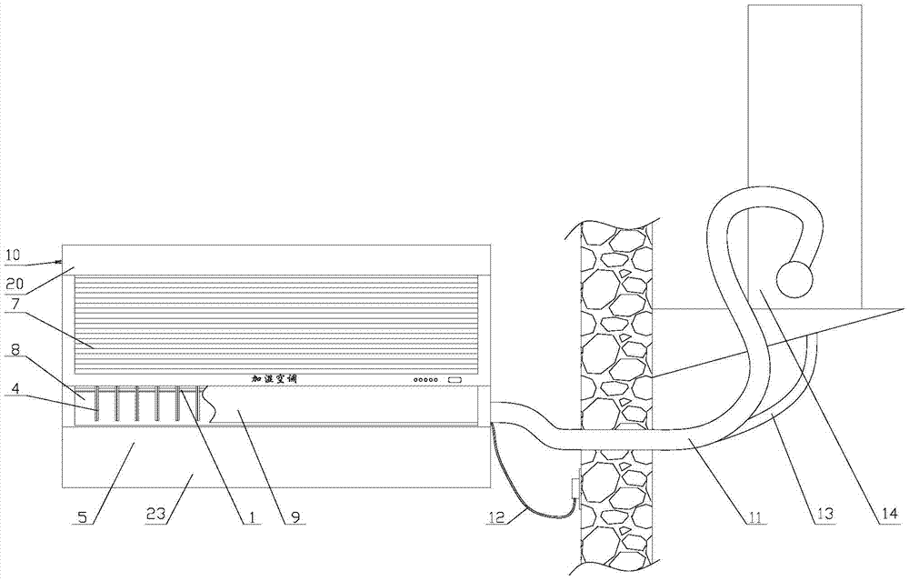
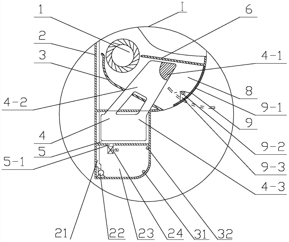
[0060] 1. Indoor humidity and temperature adjustment system, including: air duct 1, air conditioner shell 2, volute 3, water evaporation component 4, evaporation water tank 5, volute tongue 6, indoor unit 7, air duct 8, horizontal air guide strip component 9, Solenoid valve C10, connecting pipe 11, power cord 12, outdoor unit condensate pipe 13, outdoor unit 14, primary water tank 20, upstream connection pipe 21, water supply pump 22, secondary water tank 23, solenoid valve A24, downlink connection pipe 25, electromagnetic Valve B26, secondary water tank lower liquid level sensor 31, secondary water tank upper liquid level sensor 32, evaporation water tank lower liquid level sensor 33, evaporation water tank upper liquid level sensor 34, primary water tank lower liquid level sensor 35, primary water tank upper liquid level sensor 36,

[0061] It is characterized by:

[0062] The indoor humidity and temperature adjustment system is a split-type dehumidification air conditioner...

Embodiment 2

[0094] 1. Indoor humidity and temperature adjustment system, including: air duct 1, air conditioner shell 2, volute 3, water evaporation component 4, evaporation water tank 5, volute tongue 6, indoor unit 7, air duct 8, horizontal air guide strip component 9, Solenoid valve C10, connecting pipe 11, power cord 12, outdoor unit condensate pipe 13, outdoor unit 14, primary water tank 20, upstream connection pipe 21, water supply pump 22, secondary water tank 23, solenoid valve A24, downlink connection pipe 25, electromagnetic Valve B26, secondary water tank lower liquid level sensor 31, secondary water tank upper liquid level sensor 32, evaporation water tank lower liquid level sensor 33, evaporation water tank upper liquid level sensor 34, primary water tank lower liquid level sensor 35, primary water tank upper liquid level sensor 36,

[0095] It is characterized by:

[0096] The indoor humidity and temperature adjustment system is a split-type dehumidification air conditioner...


PUM


Abstract

The invention discloses an indoor humidity and temperature regulating system, and relates to the technical field of indoor humidity and temperature regulation. The indoor humidity and temperature regulating system is characterized in that a primary water tank is arranged at the upper part of an indoor part of the indoor humidity and temperature regulating system; an indoor unit is connected to the lower part of the primary water tank; an evaporation water tank is connected to the lower part of the indoor unit; a secondary water tank is connected to the lower part of the evaporation water tank; an air duct is in a volute shape; an air flow drum is arranged in the volute air duct and cylindrical; a water evaporation assembly is positioned at the air duct and parallel to two bottom surfaces of the cylindrical drum of the air flow drum; an evaporation water tank drainage pipe is connected to the bottom of the evaporation water tank; an electromagnetic valve A is mounted on the evaporation water tank drainage pipe; a water supply pump is mounted in the secondary water tank and connected with an upward communication pipe; the pipe outlet of the upward communication pipe is positioned at the upper part of the primary water tank. The indoor humidity and temperature regulating system has a humidifying function besides refrigeration and heating, and can regulate indoor temperature and indoor humidity for 24 hours.

Description

technical field [0001] An indoor humidity and temperature regulating system relates to the technical field of air conditioners. Background technique [0002] Dry air will reduce the ability of the human respiratory system to eliminate bacteria, cause upper respiratory tract infection, and then cause respiratory diseases. Dry air can make the skin rough, which is the main reason for dry Gobi people's rough skin. In addition, dry air is prone to static electricity, which also makes people feel uncomfortable. In order to increase the humidity, merchants usually use humidifiers to solve the problem, but the production cost of ultrasonic humidifiers is high, and the moisture diffuses slowly without the help of wind without flow, so the humidification effect is not ideal. [0003] CN104566631A of the prior art is an air conditioner with a humidifier "multiple heating wires are installed in the humidifier. The heating wires of the humidifier are connected to the temperature contr...

Claims


Application Information

Patent Timeline
Patent Type & Authority Patents(China)
IPC IPC(8): F24F1/00F24F13/22
CPCF24F1/0003F24F13/222F24F2013/225
Inventor 马晶张艳霞戚玉华
Owner UNIV OF JINAN
Learn More