Boiler with temperature instrument

A technology for instrumentation and temperature detectors, applied in fluid heaters, lighting and heating equipment, electromagnetic audible signals, etc.

Active Publication Date: 2021-05-18
河北蔚州能源综合开发有限公司
View PDF7 Cites 0 Cited by
  • Summary
  • Abstract
  • Description
  • Claims
  • Application Information

AI Technical Summary

Problems solved by technology

[0004] Aiming at an existing boiler with temperature instrumentation, the transfer box on the surface of the boiler absorbs the heat in the boiler. When the temperature is too high, the temperature instrumentation alarm reminds the staff to replace the water in the transfer box, and the boiler produces The temperature is very high, and it is easy to touch the drain pipe when changing the water in the transfer box, resulting in the occurrence of personnel scald accidents. The invention provides a boiler with temperature instruments to solve the above technical problems

Method used


Image

  • Boiler with temperature instrument
  • Boiler with temperature instrument
  • Boiler with temperature instrument

Examples


Embodiment 1

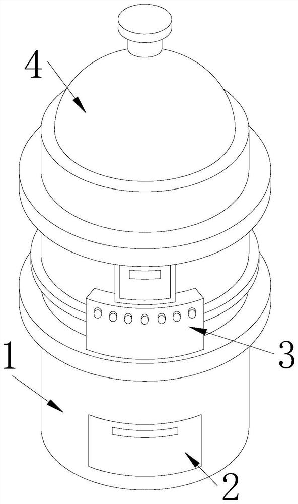
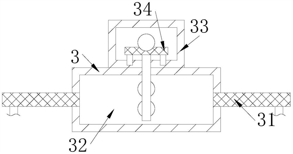
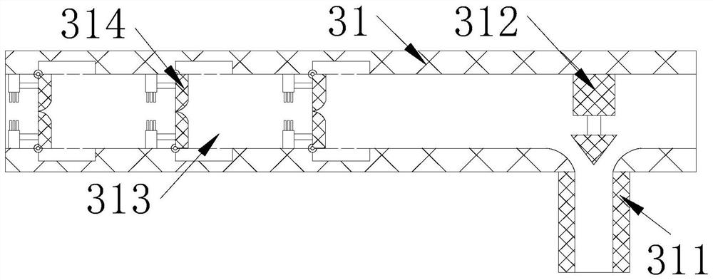
[0029] The invention provides a boiler with temperature instrumentation, the structure of which includes a boiler 1, a heating cabinet 2, a temperature detection ring 3, and an upper cover 4. 3 is nested on the outer surface of the boiler 1, the upper cover 4 is connected to the top of the boiler 1 through movable engagement, the temperature detection ring 3 includes a water guide pipe 31, a transfer box 32, an isolation box 33, and a temperature detector 34. The water guide pipe 31 is horizontally welded on the left and right sides of the temperature detection ring 3, the transfer box 32 is embedded inside the temperature detection ring 3, the bottom of the isolation box 33 is connected to the upper surface of the temperature detection ring 3 by welding, and the temperature detector 34 is embedded in the temperature detection ring 3, and the bottom of the temperature detector 34 penetrates the bottom of the isolation box 33 and is placed inside the transfer box 32. The water g...

Embodiment 2

[0035] The invention provides a boiler with temperature instrumentation, the structure of which includes a boiler 1, a heating cabinet 2, a temperature detection ring 3, and an upper cover 4. 3 is nested on the outer surface of the boiler 1, the upper cover 4 is connected to the top of the boiler 1 through movable engagement, the temperature detection ring 3 includes a water guide pipe 31, a transfer box 32, an isolation box 33, and a temperature detector 34. The water guide pipe 31 is horizontally welded on the left and right sides of the temperature detection ring 3, the transfer box 32 is embedded inside the temperature detection ring 3, the bottom of the isolation box 33 is connected to the upper surface of the temperature detection ring 3 by welding, and the temperature detector 34 is embedded in the temperature detection ring 3, and the bottom of the temperature detector 34 penetrates the bottom of the isolation box 33 and is placed inside the transfer box 32. The water g...


PUM


Abstract

The invention discloses a boiler with a temperature instrument. The boiler structurally comprises a boiler body, a heating cabinet, a temperature detection ring and an upper cover, the heating cabinet is installed at the front side of the bottom of the boiler body in a matched manner, the temperature detection ring is embedded in the outer surface of the boiler body, and the upper cover is movably connected to the top of the boiler body in a clamped manner. The boiler has the beneficial effects that the temperature of the boiler continuously rises in the using process, water in a transfer box is heated and flows into a water guide pipe, hot water and water vapor upwards push an ejecting plate through a through pipe to enter a fixed barrel, a telescopic rod pushes away a water stop device, and the hot water in a through groove is conveniently and automatically discharged through a water discharging pipe; and a detection rod transmits the temperature in the transfer box to a temperature detector for temperature detection, when the temperature in the transfer box rises, an ejector block pushes a positioning plate outwards, so that a buzzer gives a high-temperature alarm, and when the temperature in the transfer box drops, a movable plate is pulled into the inner wall of the positioning plate through the tension of a tension spring, so that the buzzer stops giving the alarm.

Description

technical field [0001] The invention relates to the field of temperature instruments, in particular to a boiler with temperature instruments. Background technique [0002] The temperature instrument is a common instrument used to detect and display the temperature. A boiler is a common machine used to generate heat. Usually, a temperature instrument is installed on the boiler to check the real-time temperature of the boiler to prevent the boiler temperature from being too high. Damaged electronic components and even cracked boilers. [0003] At present, there is an existing boiler with temperature instruments and meters. The transfer box on the surface of the boiler absorbs the heat in the boiler. The temperature is very high, and it is easy to touch the drain pipe when changing the water in the transfer box, resulting in the occurrence of personnel scalding accidents. Contents of the invention [0004] Aiming at an existing boiler with temperature instrumentation, the t...

Claims


Application Information

Patent Timeline
Patent Type & Authority Applications(China)
IPC IPC(8): F24H9/20G08B3/10
CPCF24H9/2007G08B3/10
Inventor 陈芳
Owner 河北蔚州能源综合开发有限公司
Why Eureka
Try Eureka