Centrifugal model test device and method for researching underground diaphragm wall construction environment effect
A technology of centrifugal model test and underground diaphragm wall, which is applied in the direction of soil material test and material inspection product, and can solve problems such as difficult simulation
Active Publication Date: 2021-05-18
ZHEJIANG UNIV
View PDF20 Cites 2 Cited by
- Summary
- Abstract
- Description
- Claims
- Application Information
AI Technical Summary
Problems solved by technology
However, due to the difficulty of simulating the excavation and concrete pouring of the underground diaphragm wall in the centrifugal model test, the centrifugal model test method is used to study
Method used
View moreImage
Smart ImageViewing Examples
Examples
 PUM
| Property | Measurement | Unit |
|---|---|---|
| Tensile strength | aaaaa | aaaaa |
| The average particle size | aaaaa | aaaaa |
| Thickness | aaaaa | aaaaa |
Abstract
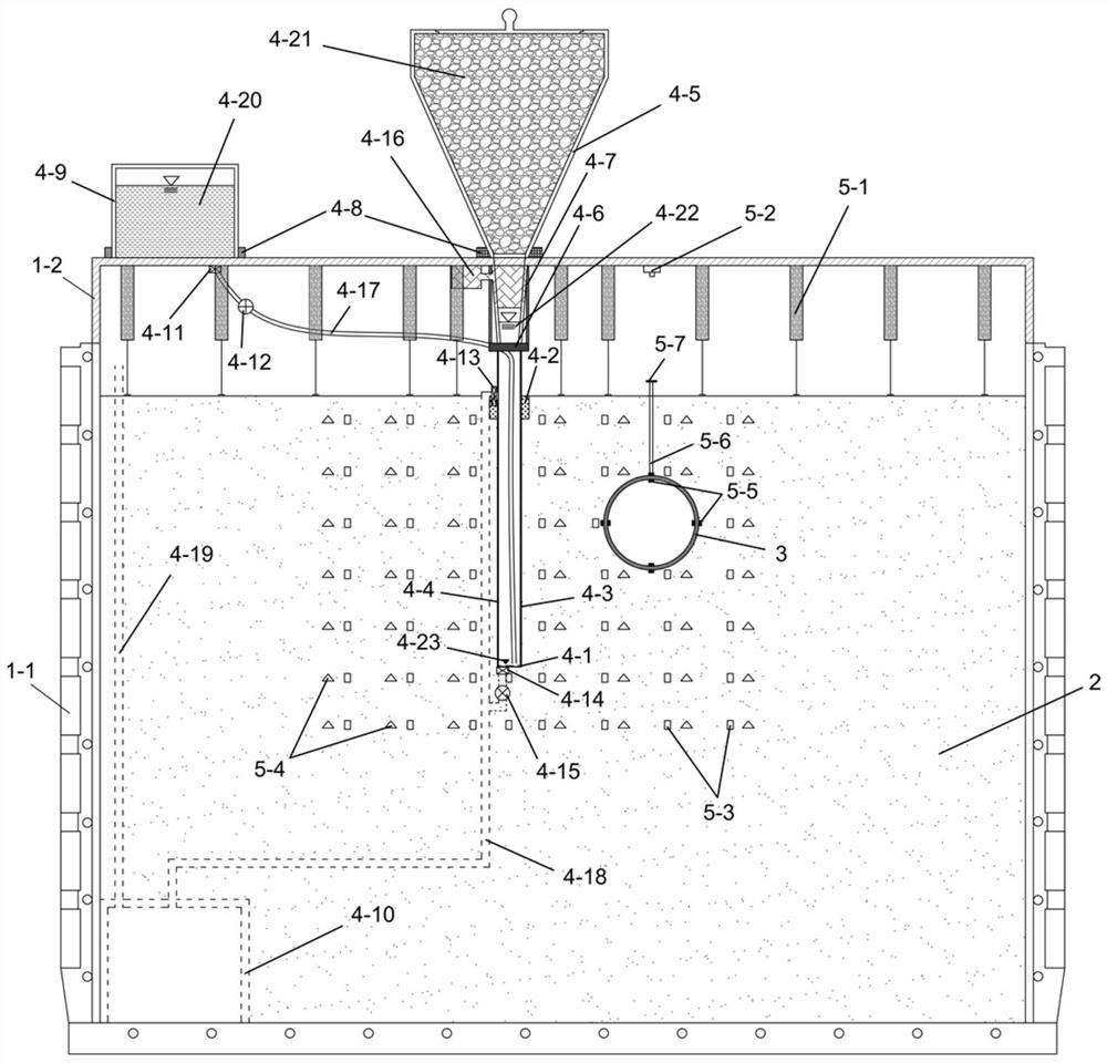
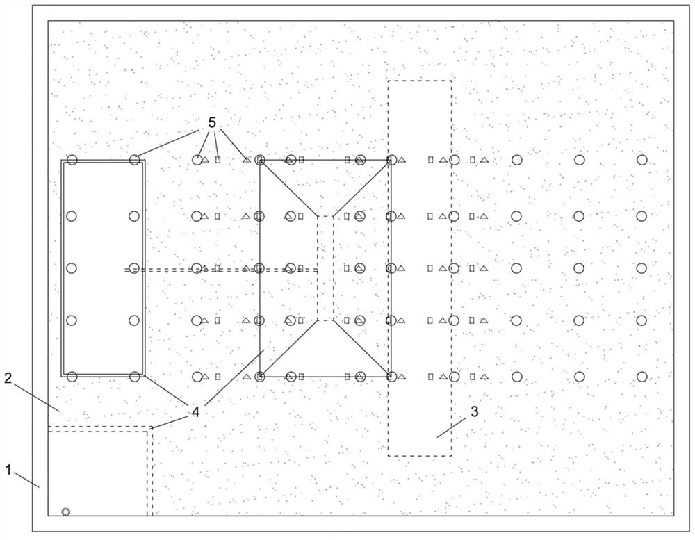
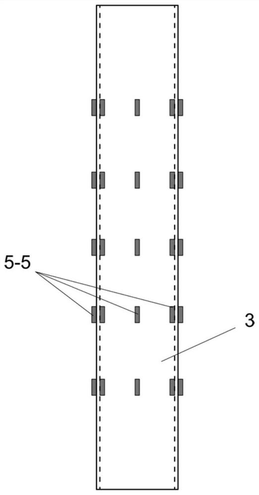
The invention discloses a centrifugal model test device and method for researching an underground diaphragm wall construction environment effect. The device comprises a model box, model soil, a model tunnel, an underground diaphragm wall construction simulation system and an environment effect measurement system. The test device can be used for researching the influence effect of underground diaphragm wall construction on mechanical behaviors of surrounding stratums and near shallow buried pipelines or shield tunnels and the internal mechanism of the underground diaphragm wall construction. The sodium chloride solution is adopted to simulate the slurry adopted in the grooving construction process of the underground diaphragm wall, the method has the advantages that materials are easy to obtain, low in price, environmentally friendly, convenient to control heavily, safe, harmless and the like, and the problem of high corrosivity when a zinc chloride solution is used is effectively avoided; by regulating and controlling the liquid level of the sodium chloride solution to exceed the height of the surface of the model soil or to be flush with the surface of the model soil, the initial ground stress acting on the groove position of the underground diaphragm wall before excavation of the underground diaphragm wall can be conveniently and accurately represented or the soil pressure unloading effect in the grooving construction process of the underground diaphragm wall can be simulated.
Description
technical field [0001] The invention belongs to the field of deep foundation pit engineering, in particular to a centrifugal model test device and method for studying the environmental effect of underground diaphragm wall construction. Background technique [0002] Since the underground diaphragm wall technology was introduced into the field of deep foundation pit engineering in my country in the 1950s, it has been widely used and developed to a certain extent. Chinese invention patent (authorized publication number CN110158575B) discloses a method for constructing an underground diaphragm wall, which has the advantages of fewer construction joints and low probability of leakage. Chinese utility model patent (authorized publication number CN211948373U) discloses a kind of joint structure of prefabricated underground diaphragm wall, and this joint structure has the advantages of simple overall structure and convenient operation. The Chinese invention patent (application publ...
Claims
Login to View More Application Information
Patent Timeline
 IPC IPC(8): G01N33/24
CPCG01N33/24
Inventor 郭盼盼龚晓南
Owner ZHEJIANG UNIV
Features
- R&D
- Intellectual Property
- Life Sciences
- Materials
- Tech Scout
- Unparalleled Data Quality
- Higher Quality Content
- 60% Fewer Hallucinations
Learn More Browse by: Latest US Patents, China's latest patents, Technical Efficacy Thesaurus, Application Domain, Technology Topic, Popular Technical Reports.
© 2025 PatSnap. All rights reserved.Legal|Privacy policy|Modern Slavery Act Transparency Statement|Sitemap|About US| Contact US: help@patsnap.com


